
Auto-calibrated scanning-angle prism-type total internal reflection microscopy for nanometer-precision axial position determination and optional variable-illumination-depth pseudo total internal reflection microscopy

Inactive Publication Date: 2015-04-21
IOWA STATE UNIV RES FOUND
View PDF16 Cites 16 Cited by
  • Summary
  • Abstract
  • Description
  • Claims
  • Application Information

AI Technical Summary

Benefits of technology

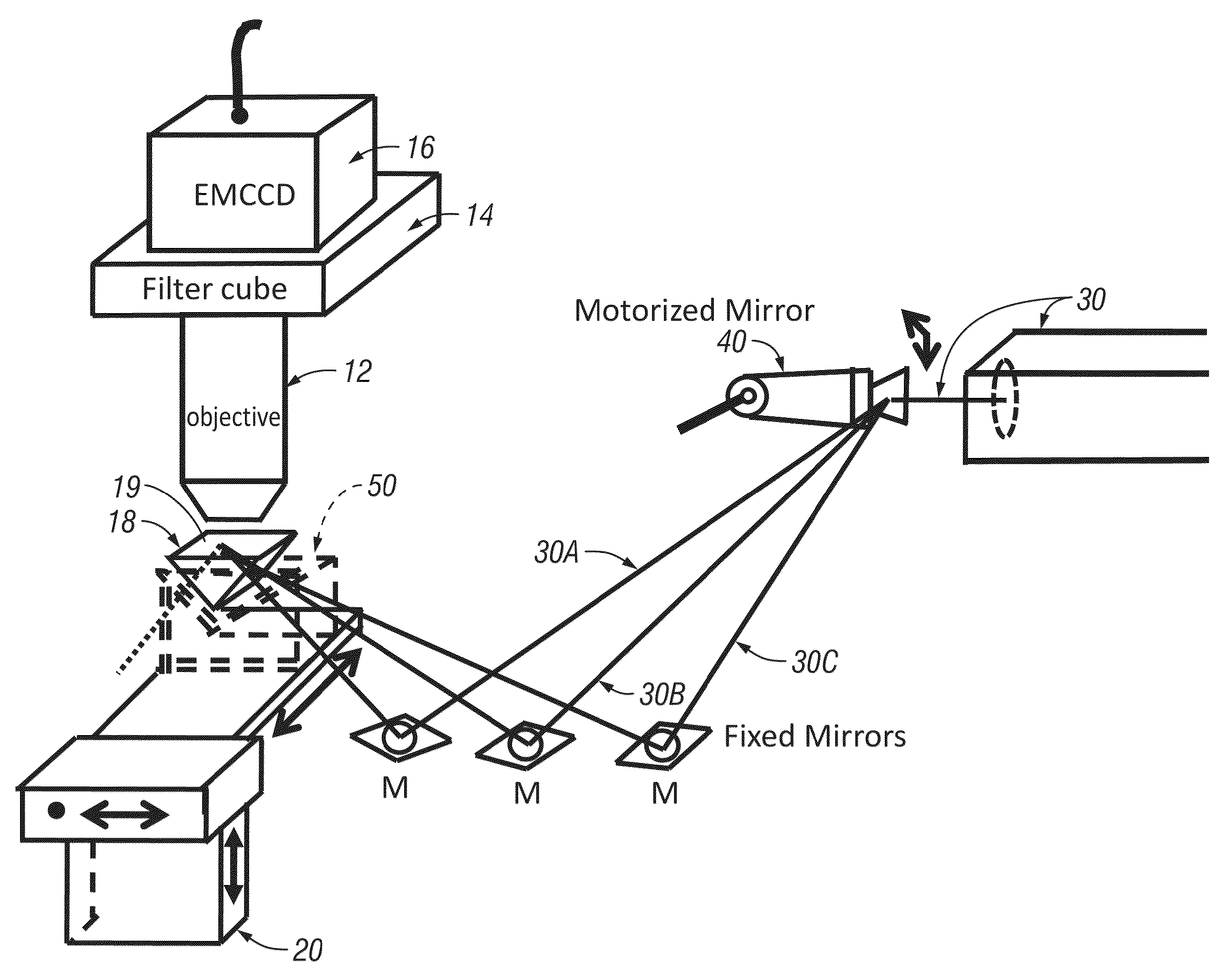
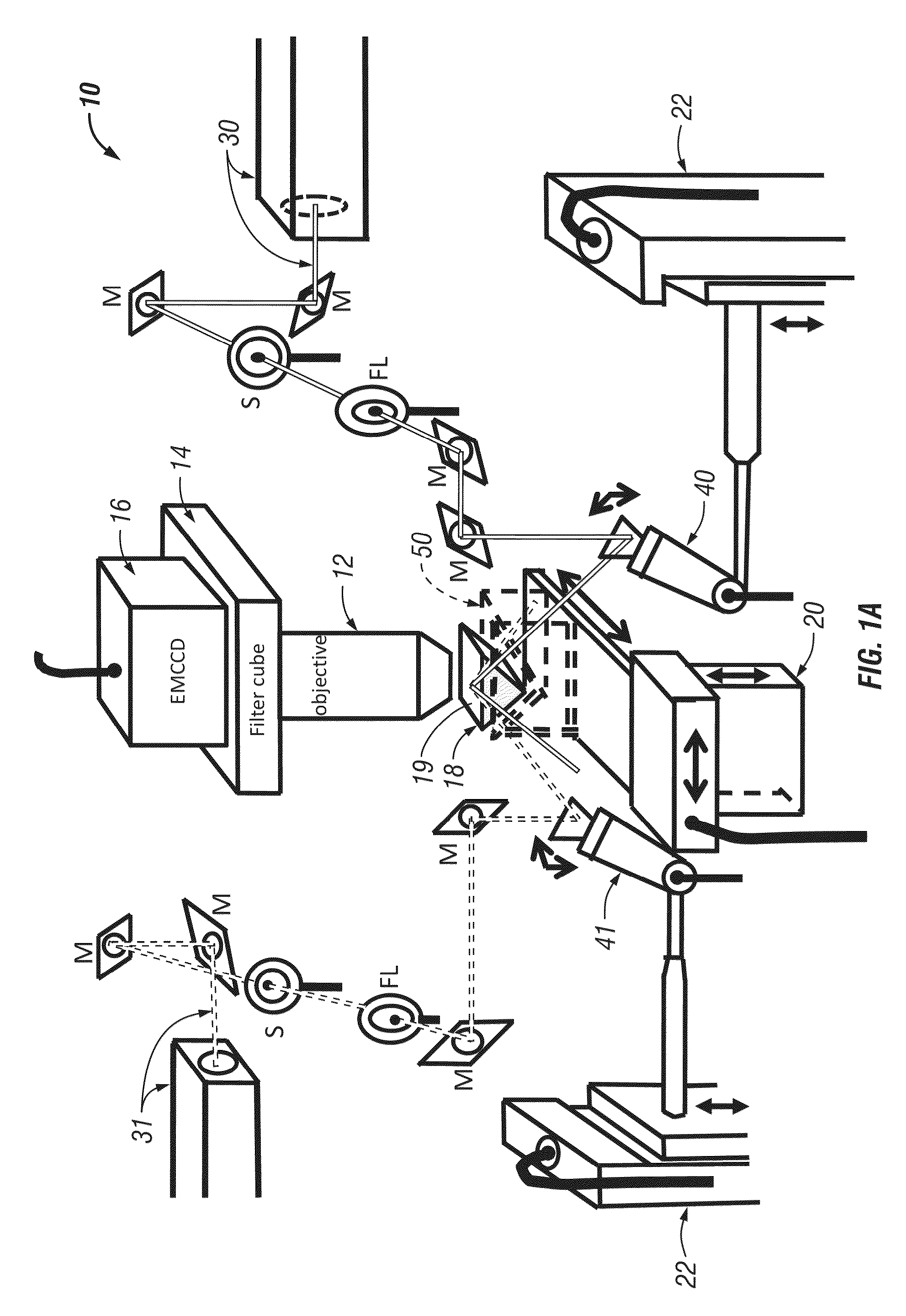
The present invention provides improvements to a VA-TIRM system for creating evanescent fields. The system can quickly and automatically create an effect for any incident angle and can calibrate and scan with multiple light sources. The optical trapping forces created by the evanescent field can also be fine-adjusted.

Problems solved by technology

Also, the objective configuration can result in limitations of available angle range for incident illumination light.
However, the systems are quite expensive.
Additionally, they require drying and exposure of the sample to vacuum.
But there are issues with present VA-TIRFM technology.
This limits the through-put and efficiency of such systems.
It also exposes such systems to unintentional human error.
The theoretical spatial resolution of evanescent field (EF) excitation has not been harvested because it is difficult or impossible to manually calibrate the system at all relevant incident angles within small margins of error.
Also, use of such TIRFM systems for 3D image reconstruction has been hampered by difficulties performing full Laplace transforms or fitting with nonlinear least squares methods.
Many TIRFM systems do not have any systematic way to step the excitation plane through the sample.
Another issue that arises with TIRFM are limitations regarding illumination depth.

Method used


Image

  • Auto-calibrated scanning-angle prism-type total internal reflection microscopy for nanometer-precision axial position determination and optional variable-illumination-depth pseudo total internal reflection microscopy
  • Auto-calibrated scanning-angle prism-type total internal reflection microscopy for nanometer-precision axial position determination and optional variable-illumination-depth pseudo total internal reflection microscopy
  • Auto-calibrated scanning-angle prism-type total internal reflection microscopy for nanometer-precision axial position determination and optional variable-illumination-depth pseudo total internal reflection microscopy

Examples


embodiment two

References Re Embodiment Two

[0159](1) Holz, R. W.; Axelrod, D. Secretory granule behaviour adjacent to the plasma membrane before and during exocytosis: total internal reflection fluorescence microscopy studies. Acta Physiol. 2008, 192, 303.[0160](2) Axelrod, D. Total Internal Reflection Fluorescence Microscopy. In Biophysical Tools for Biologists, Volume Two: In Vivo Techniques; 1 ed.; Correia, J. J., Detrich, H. W., Eds.; Academic Press: 2008; Vol. 89, p 169.[0161](3) Axelrod, D.; Omann, G. M. Combinatorial microscopy. Nat. Rev. Mol. Cell. Biol. 2006, 7, 944.[0162](4) Chen, I.; Ting, A. Y. Site-specific labeling of proteins with small molecules in live cells. Curr. Opin. Biotechnol. 2005, 16, 35.[0163](5) Lang, E.; Baier, J.; Kohler, J. Epifluorescence, confocal and total internal reflection microscopy for single-molecule experiments: a quantitative comparison. J. Microsc.-Oxf. 2006, 222, 118.[0164](6) Wazawa, T.; Ueda, M. Total internal reflection fluorescence microscopy in singl...


PUM


Abstract

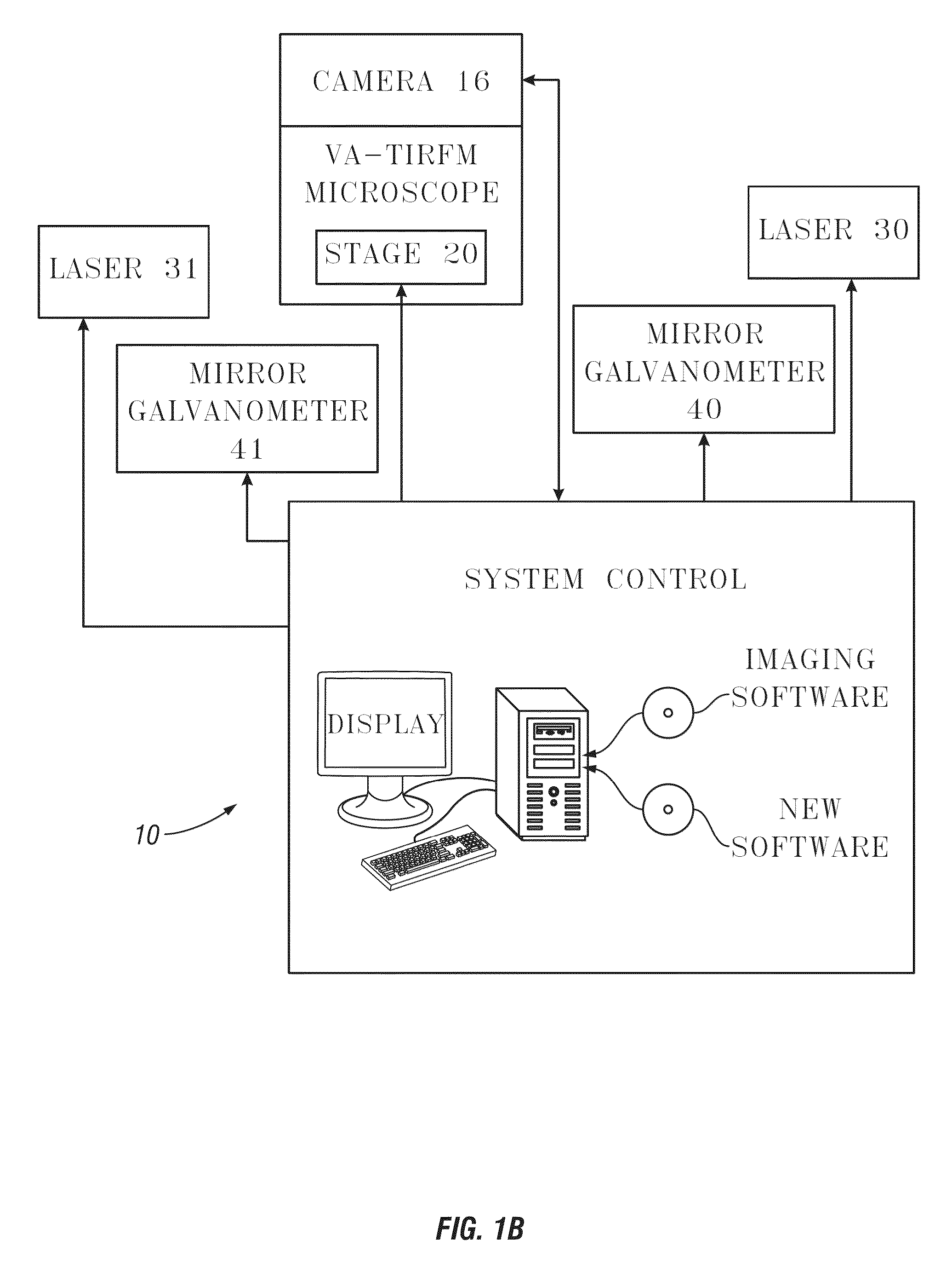
A method, apparatus, and system for improved VA-TIRFM microscopy. The method comprises automatically controlled calibration of one or more laser sources by precise control of presentation of each laser relative a sample for small incremental changes of incident angle over a range of critical TIR angles. The calibration then allows precise scanning of the sample for any of those calibrated angles for higher and more accurate resolution, and better reconstruction of the scans for super resolution reconstruction of the sample. Optionally the system can be controlled for incident angles of the excitation laser at sub-critical angles for pseudo TIRFM. Optionally both above-critical angle and sub critical angle measurements can be accomplished with the same system.

Description

CROSS-REFERENCE TO RELATED APPLICATIONS[0001]This application claims priority under 35 U.S.C. §119 to provisional application Ser. No. 61 / 295,568 filed Jan. 15, 2010 and Ser. No. 61 / 384,095 filed Sep. 17, 2010, herein incorporated by reference in their entireties.GRANT REFERENCE[0002]This invention was made with government support under Contract No. DE-AC02-07CH11358 awarded by U.S. Department of Energy. The government has certain rights in the invention.I. BACKGROUND OF THE INVENTION[0003]A. Field of the Invention[0004]The present invention relates to microscopy and, in particular, to total internal reflection microscopy (TIRM) and to prism-type variable-angle TIRM (sometimes referred to as VA-TIRM). The invention can include a pseudo total internal reflection microscopy mode. One type of TIRM 15 TIRFM (Total Internal Reflection Fluorescence Microscopy (conventional or pseudo)), which creates an evanescent field (EF) and gathers fluorescence generated by the EF. Another type of TIR...

Claims


Application Information

Patent Timeline
IPC IPC(8): G01N21/64
CPCG01N21/6428G01N21/6458G01N21/648G02B21/16G02B21/26
Inventor FANG, NINGSUN, WEI
Owner IOWA STATE UNIV RES FOUND
Learn More