
Caliper for measuring objects in an image

a technology for measuring objects and images, applied in the field of image analysis, can solve the problem that the measurement of the size of objects may be less accurate, and achieve the effect of improving the visualization of anatomical measuremen

Active Publication Date: 2015-04-21
KONINKLIJKE PHILIPS ELECTRONICS NV
View PDF21 Cites 81 Cited by
  • Summary
  • Abstract
  • Description
  • Claims
  • Application Information

AI Technical Summary

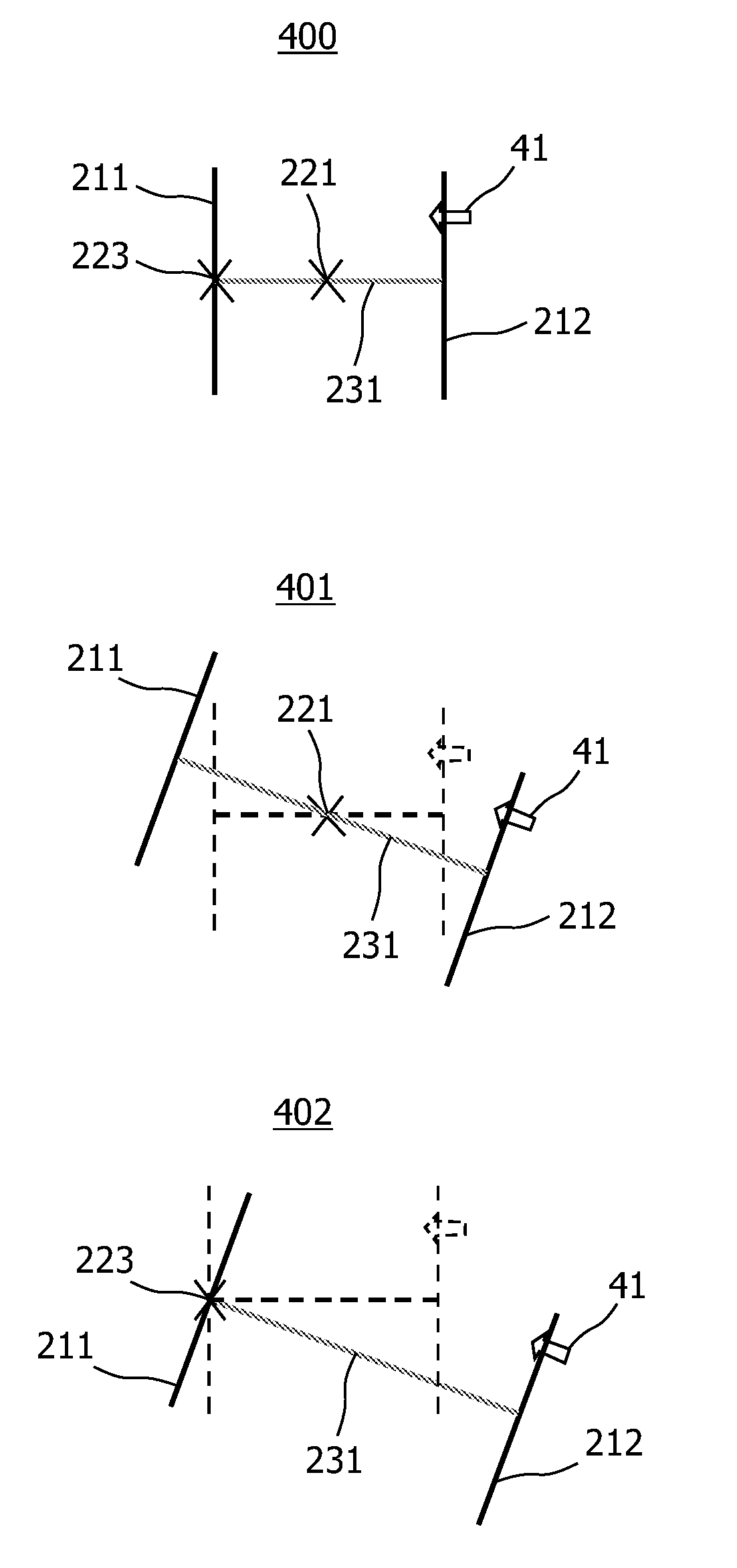
Benefits of technology

[0006]It would be advantageous to have a system that improves visualizing a measurement of an anatomical or pathological structure.
[0011]Viewing the first and second planar surfaces of the caliper, visualized together with the measured object, improves the visualization of the measurement of an anatomical or pathological structure, because the first and second planar surface help a user to relate the measurement to the object.
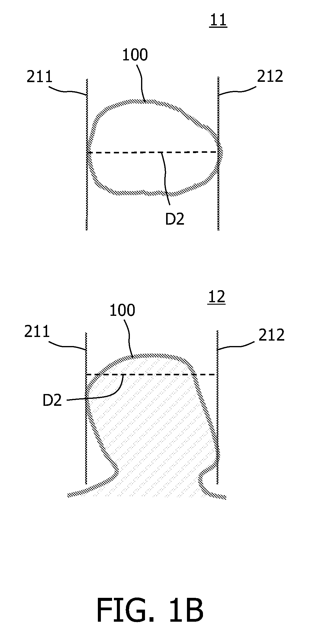
[0012]In an embodiment, the system further comprises a manipulation unit for manipulating the caliper in the image data space. Manipulations comprise translations, rotations and scaling of the caliper. Scaling of the caliper may be isotropic or directional. The manipulations allow to better position the caliper relative to the object and may thus improve performing the measurement, because it is easier to see what is being measured. Advantageously, the size of the object measured by the system of the invention is often more accurate. FIG. 1B schematically illustrates a manually measured polyp size according to the invention. In a top view 11, the first and second surface 211 of the caliper and 212, respectively, is adjacent to a contour 100 which is assumed to represent a projection of the polyp on a plane perpendicular to the viewing direction. The distance D2 between the two surfaces 211 and 212 is accepted as the size of the polyp. This is in agreement with a definition of the polyp size described in an article by N. Gopalswamy et al., entitled “Is in vivo measurement of size of polyps during colonoscopy accurate?”, published in Gastrointestinal Endoscopy 46 (1997), no. 6, pages 497-502. A side view 12 further illustrates the distance D2 measured by the caliper of the invention.
[0014]In an embodiment of the system, the caliper further comprises a caliper axis. The caliper axis may be a rotation axis of the caliper. The caliper axis may further improve aligning the caliper with the measured object, in particular with an object having its own axis.
[0015]In an embodiment of the system, the deployment unit is further arranged for aligning the caliper axis with an axis of the object. This makes aligning the caliper with an axis of the object, e.g., with a colon polyp axis, easier for the user of the system.

Problems solved by technology

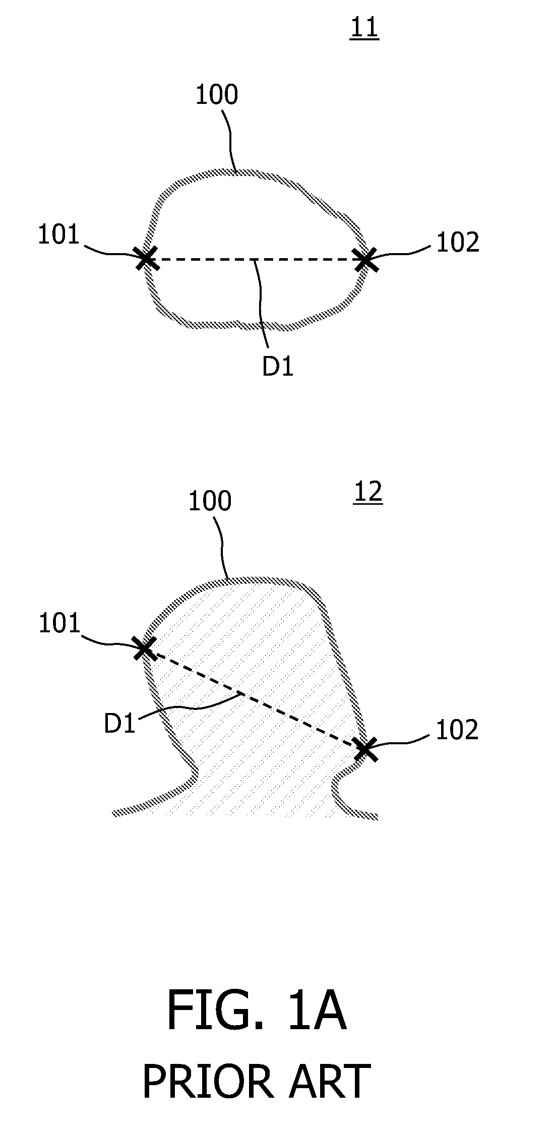
Further, in a manual approach, the measured size of the object may be less accurate. FIG. 1A schematically illustrates a manually measured polyp size according to prior art.

Method used


Image

  • Caliper for measuring objects in an image
  • Caliper for measuring objects in an image
  • Caliper for measuring objects in an image

Examples


Embodiment Construction

[0042]FIG. 2 illustrates exemplary embodiments of the caliper of the invention. A first embodiment 21 of the caliper comprises a first planar surface 211 and a second planar surface, substantially parallel to the first planar surface 212. The first and second planar surface are both a rectangle. The rectangles are aligned with each other, i.e., the line determined by a pair of corresponding vertices of the first and second planar surface is substantially perpendicular to the first and second planar surface. The skilled person will understand that other shapes and / or alignments are also possible and that the scope of the invention is not limited by the shape and alignment of the first and second planar surface used to illustrate the invention. For example, in an embodiment, the first and second planar surface may be a triangle or a circle. In an embodiment, a circle of the first planar surface may have a radius different from, or may be not coaxial with, a circle of the second planar...


PUM


Abstract

The invention relates to a system (300) for performing and visualizing a measurement of an object viewed in an image computed from image data, the system comprising an image unit (310) for visualizing the image data in the image for displaying in a display, a deployment unit (320) for deploying a caliper (21; 22; 23; 24) in an image data space based on the location of the object in the image data space, and a caliper unit (330) for visualizing the caliper (21; 22; 23; 24) in the image, wherein the caliper (21; 22; 23; 24) comprises a first planar surface (211) and a second planar surface (212) substantially parallel to the first planar surface (211), and wherein the measurement of the object is determined based on the distance between the planes of the first and second planar surface. Viewing the first and second planar surfaces of the caliper, visualized together with the measured object, improves the visualization of the measurement of an anatomical or pathological structure, because the first and second planar surface help a user to relate the measurement to the object—to see what is being measured. Advantageously, in an embodiment of the system (300), manually aligning the first and second planar surface with the object may also improve capturing the size of the object, because the system makes the measurement both easier to obtain and more accurate.

Description

FIELD OF THE INVENTION[0001]The invention relates to the field of image analysis and, more specifically, to measuring structures viewed in images.BACKGROUND OF THE INVENTION[0002]Computed Tomography (CT) colonoscopy, also known as virtual colonoscopy, is a technique for detecting polyps in the colon. Colon cancer is often preceded by the presence of a benign polyp before it becomes malignant. The size of a polyp is important because it helps predict the likelihood of malignancy. The measured size of a polyp in CT colonography images is used to determine the action a patient has to undergo after examination.[0003]Currently, the polyp size on two-dimensional (2D) or three-dimensional (3D) colonography images may be measured manually by measuring the distance between two points placed at two locations on the polyp base visualized in an image. The CT colonography software computes the Euclidean distance between the two points. When using a 2D image to perform the measurement, e.g., on a...

Claims


Application Information

Patent Timeline
Patent Type & Authority Patents(United States)
IPC IPC(8): G06K9/00A61B5/107G06T7/00G06T7/60G06T19/00
CPCA61B5/1072G06T7/0012G06T7/602G06T19/00G06T2219/012G06T7/62
Inventor TRUYEN, ROELPETERS, JOOST FREDERIKVAN DER KRAAN, ROEL
Owner KONINKLIJKE PHILIPS ELECTRONICS NV
Learn More