Magnetic resonance imaging apparatus

a magnetic resonance imaging and apparatus technology, applied in the field of magnetic resonance imaging apparatus, can solve the problems of poor versatility, difficult to improve the quality of images, and significant body motion artifacts, and achieve the effect of high versatility and improved image quality

Active Publication Date: 2015-04-21
GE MEDICAL SYST GLOBAL TECH CO LLC
View PDF17 Cites 9 Cited by
  • Summary
  • Abstract
  • Description
  • Claims
  • Application Information

AI Technical Summary

Benefits of technology

[0011]Therefore, an object of the present invention is to provide a magnetic resonance imaging apparatus which is highly versatile and can improve the quality of images.
[0014]According to the present invention, it is possible to provide a magnetic resonance imaging apparatus which is highly versatile and can improve the quality of images.

Problems solved by technology

However, since a plurality of images are picked up at a plurality of timings and the MRA images are created by using the difference values between the images by the FBI method, if the subject moves its body in the course of imaging, body motion artifacts will arise significantly, and images may be blurred by T2 attenuation in the direction of phase encoding, possibly posing a difficulty to improve the quality of images.
In other imaging methods, in addition to the problem noted above, the imaging area is restricted, resulting in poor versatility.

Method used


Image

  • Magnetic resonance imaging apparatus
  • Magnetic resonance imaging apparatus
  • Magnetic resonance imaging apparatus

Examples


Embodiment Construction

[0036]Mode for Implementation 1

[0037]Mode for Implementation 1 pertaining to the present invention will be described.

[0038](Hardware Configuration)

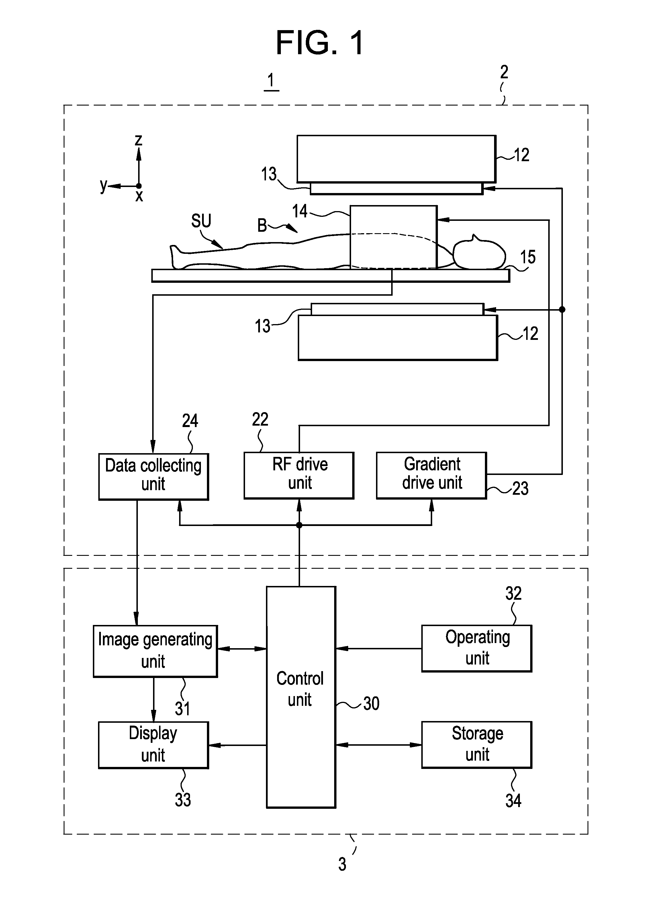
[0039]FIG. 1 is a configurational diagram showing the configuration of a magnetic resonance imaging apparatus 1 in Mode for Implementation 1 pertaining to the invention.

[0040]As shown in FIG. 1, the magnetic resonance imaging apparatus 1 in this mode for implementation has a scanning unit 2 and an operation console unit 3.

[0041]The scanning unit 2 will be described.

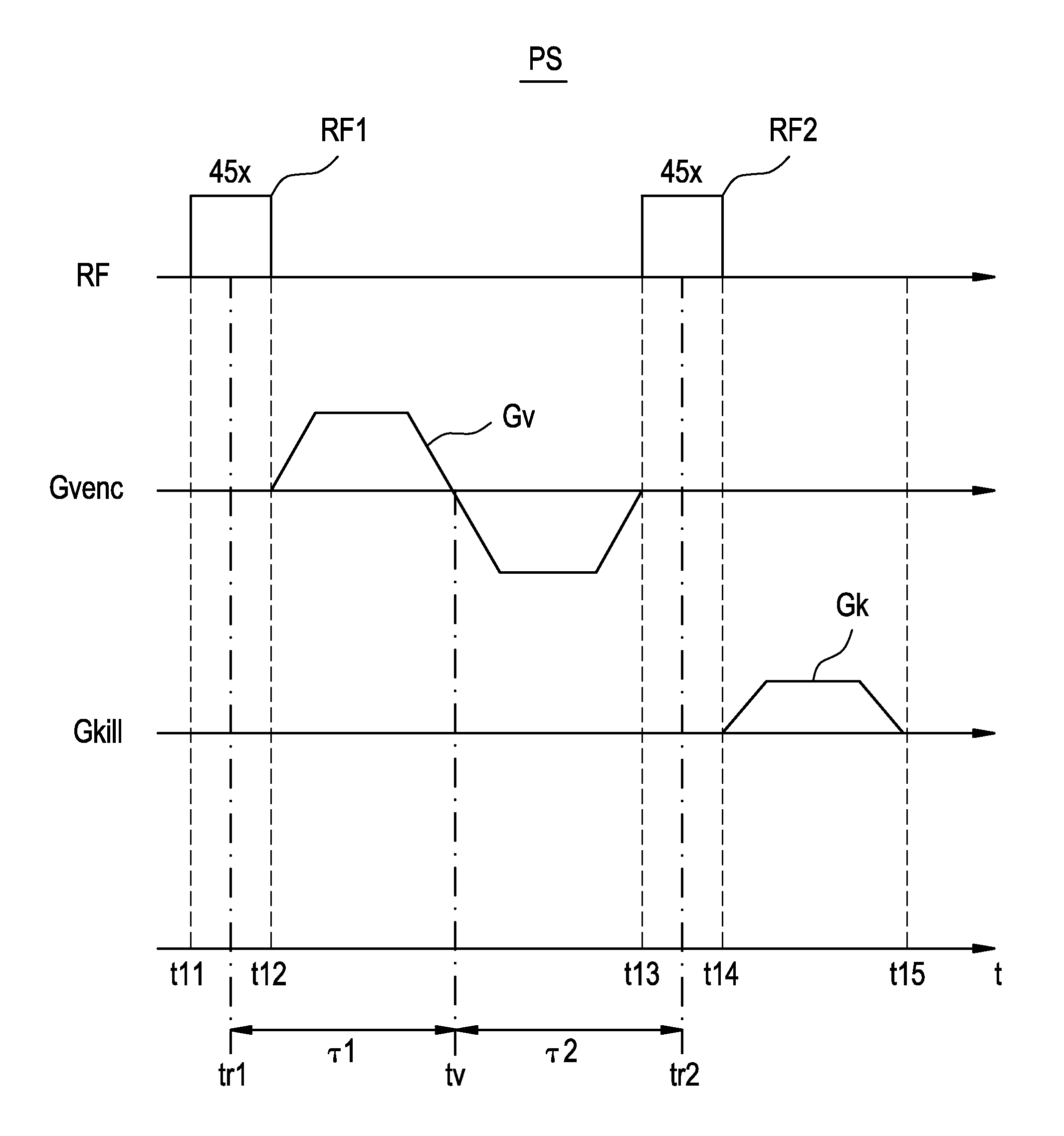
[0042]The scanning unit 2 has, as shown in FIG. 1, has a magnetostatic magnet unit 12, a gradient coil unit 13, an RF coil unit 14, a cradle 15, an RF drive unit 22, a gradient drive unit 23 and a data collecting unit 24. The scanning unit 2 transmits RF pulses to a subject SU so as to excite spinning of the subject SU in an imaging space B in which a magnetostatic field is formed, and performs an imaging sequence IS in which magnetic resonance signals generated in the subject ...


PUM


Abstract

Versatility and the quality of images are to be improved. As preparation pulses, a first RF pulse to flip along the yz plane spins oriented in a magnetostatic field direction in a subject; a velocity encoding gradient pulse which, in spins flipped by that first RF pulse, mutually shifts the phase of spins in a static state and the phase of spins in a moving state; and a second RF pulse to flip along the yz plane spins whose phase has been shifted by the velocity encoding gradient pulse are successively transmitted. After that, a killer pulse is transmitted to extinguish the transverse magnetizations of the spins flipped by the second RF pulse.

Description

CROSS REFERENCE TO RELATED APPLICATIONS[0001]This application claims the benefit of Japanese Application No. 2005-370595 filed Dec. 22, 2005 and Japanese Application No. 2006-243203 filed Sep. 7, 2006.BACKGROUND OF THE INVENTION[0002]The present invention relates to a magnetic resonance imaging apparatus, and to a magnetic resonance imaging apparatus which transmits RF pulses to a subject in a magnetostatic space, performs an imaging sequence in which magnetic resonance signals generated by transmitting gradient pulses to the subject to which the RF pulses are transmitted are obtained as imaging data, and an image of the subject is generated on the basis of the imaging data obtained by the performance of the imaging sequence.[0003]Magnetic resonance imaging (MRI) apparatuses are used in many different fields including medical and industrial purposes.[0004]A magnetic resonance imaging apparatus excites spins of protons in a subject in a magnetostatic space by a nuclear magnetic reson...

Claims


Application Information

Patent Timeline
Patent Type & Authority Patents(United States)
IPC IPC(8): A61B5/05A61B5/055G01R33/483G01R33/563
CPCG01R33/56308G01R33/5635A61B5/055G01R33/4838
Inventor MIYOSHI, MITSUHARU
Owner GE MEDICAL SYST GLOBAL TECH CO LLC
Why Eureka
Try Eureka