Frequency and bandwidth tunable microwave filter

a frequency and bandwidth tunable, microwave filter technology, applied in the field of microwave filters, can solve the problems of inability to adjust the “tuneability” of such filters, inability to achieve substantial bandwidth shift, and inability to adjust the bandwidth,

Active Publication Date: 2015-04-28
MAXAR SPACE LLC
View PDF7 Cites 1 Cited by
  • Summary
  • Abstract
  • Description
  • Claims
  • Application Information

AI Technical Summary

Problems solved by technology

In the absence of the present teachings, the “tuneability” of such filters is limited.
Such a substantial shift in bandwidth is unacceptable for, at least, satellite communications payloads, where constant, highly controlled bandwidth and spectral passband characteristics are required.
Such an approach suffers from the disadvantage of introducing additional microwave components with the attendant undesirable extra volume, extra weight, cost and complexity.
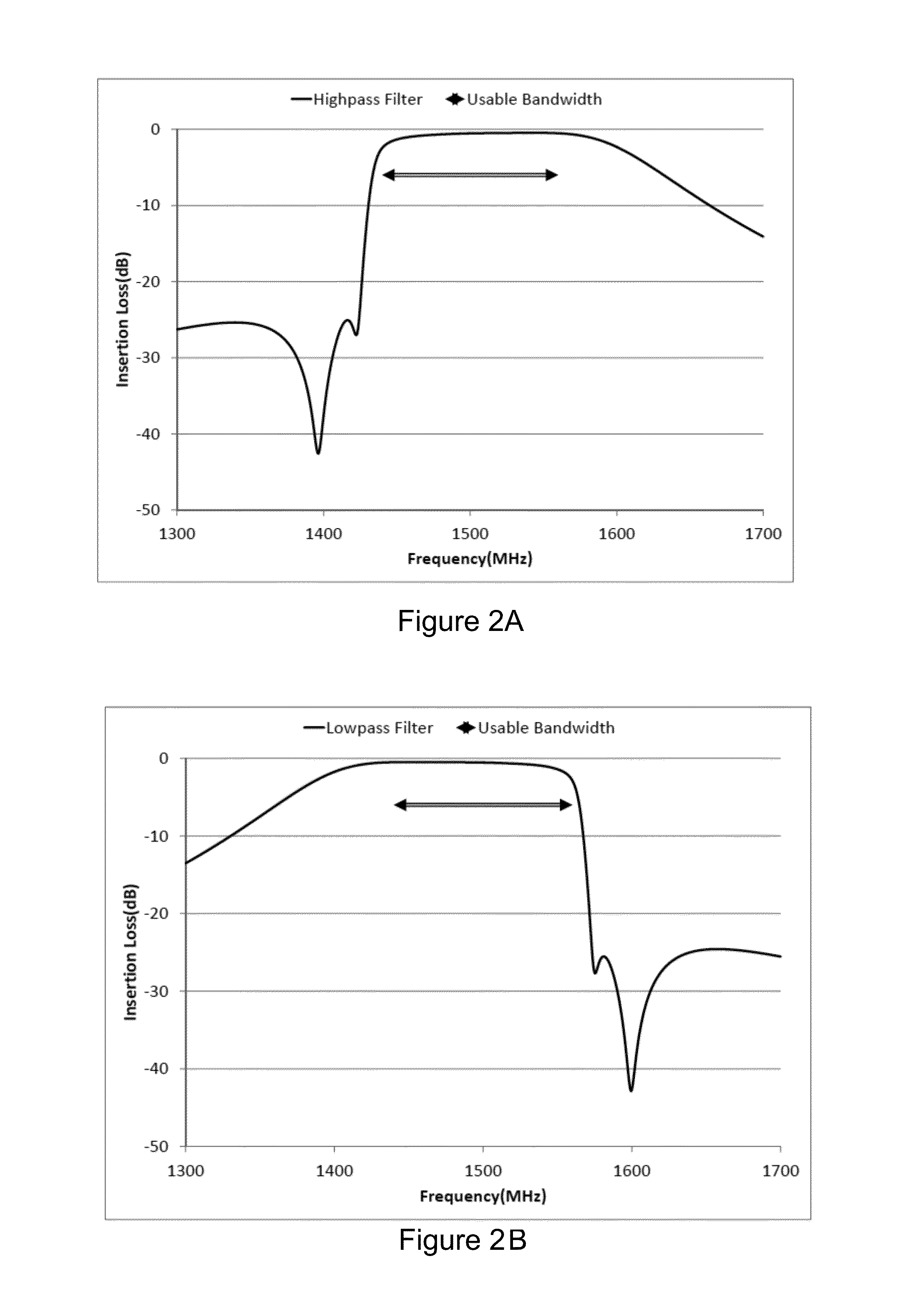
The disadvantage of this approach is that fixed low pass and high pass filters, due to their inherent very wide bandwidth, require many resonator elements to achieve necessary rejection characteristics with an attendant undesirable extra volume, extra mass and extra cost.

Method used


Image

  • Frequency and bandwidth tunable microwave filter
  • Frequency and bandwidth tunable microwave filter
  • Frequency and bandwidth tunable microwave filter

Examples


Embodiment Construction

[0026]Specific exemplary embodiments of the invention will now be described with reference to the accompanying drawings. This invention may, however, be embodied in many different forms, and should not be construed as limited to the embodiments set forth herein. Rather, these embodiments are provided so that this disclosure will be thorough and complete, and will fully convey the scope of the invention to those skilled in the art.

[0027]It will be understood that when an element is referred to as being “connected” or “coupled” to another element, it can be directly connected or coupled to the other element, or intervening elements may be present. Furthermore, “connected” or “coupled” as used herein may include wirelessly connected or coupled. It will be understood that although the terms “first” and “second” are used herein to describe various elements, these elements should not be limited by these terms. These terms are used only to distinguish one element from another element. Thus...


PUM


Abstract

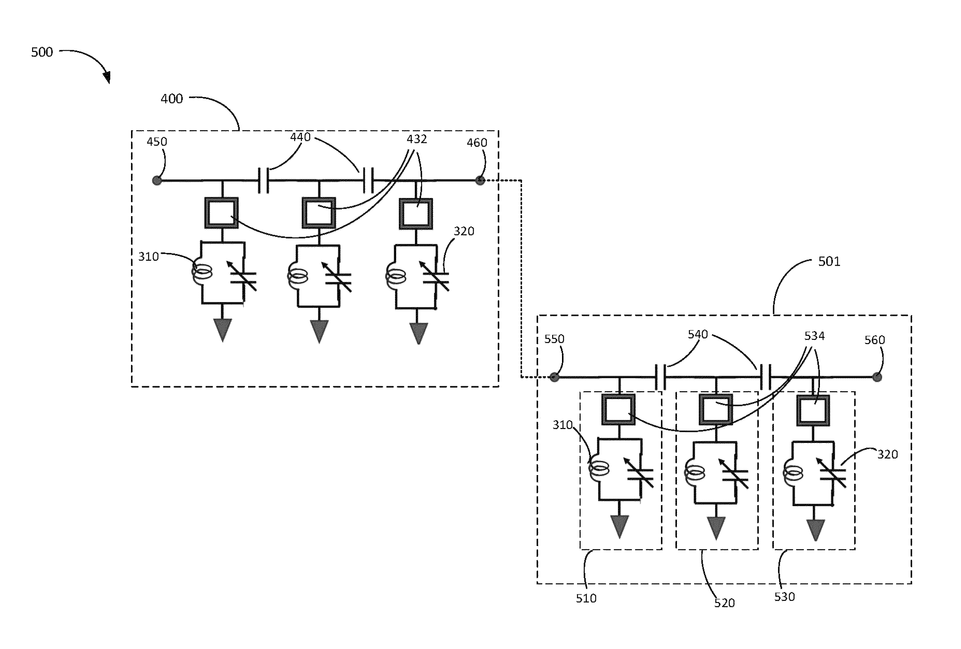
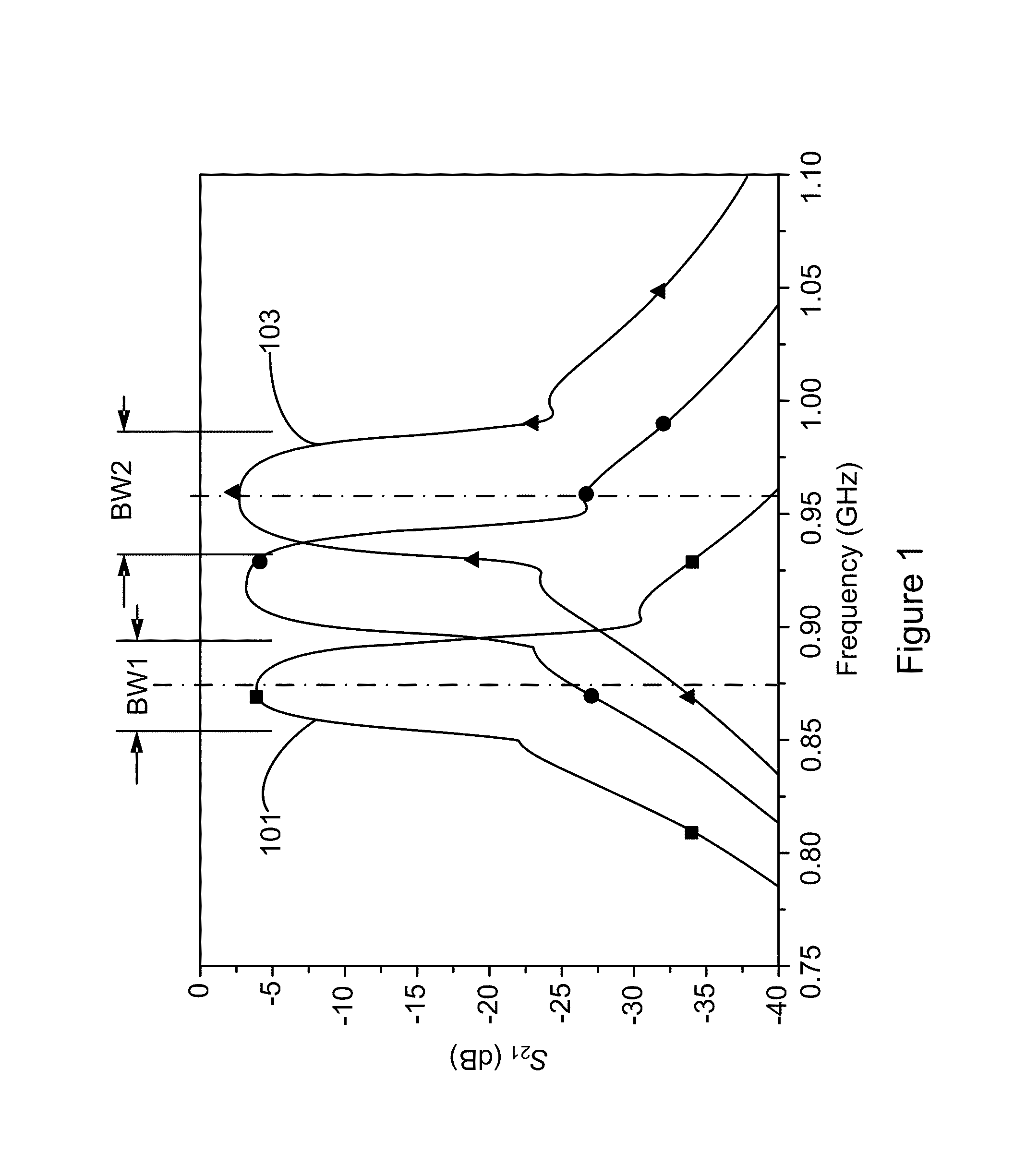
An RF bandpass filter includes a cascaded series of a first subfilter and a second subfilter. Each subfilter includes a respective inverter, voltage-controlled capacitor and inductor. A first selected one of the first subfilter and the second subfilter is a pseudo low pass filter and a second selected one of the first subfilter and the second subfilter is a pseudo high pass filter. The RF bandpass filter is configured to separately control a bandwidth and center frequency of output RF energy. The bandwidth may be controlled to be substantially fixed over a significant substantial range. The center frequency and bandwidth are controlled by adjusting a voltage input to one or more of the voltage-controlled capacitors.

Description

CROSS-REFERENCE TO RELATED APPLICATION[0001]The present patent application claims the priority benefit of commonly owned U.S. provisional patent application 61 / 607,819, filed Mar. 7, 2012, entitled “Frequency and Bandwidth Tunable Microwave Filter”, which is hereby incorporated by reference in its entirety into the present patent application.TECHNICAL FIELD[0002]This invention relates generally to a microwave filter, and particularly to a voltage tunable RF bandpass filter having separately controlled center frequency and bandwidth.BACKGROUND[0003]The assignee of the present invention manufactures and deploys spacecraft for, inter alia, communications and broadcast services from geosynchronous orbit. A substantial number of radio frequency (RF) filters are required in such spacecraft. For example, a satellite input multiplexer may utilize a number of such filters, each filter having the functionality of separating and isolating a specific respective signal or bandwidth frequency fro...

Claims


Application Information

Patent Timeline
Patent Type & Authority Patents(United States)
IPC IPC(8): H01P5/12H01P1/20H03H7/46H01P1/215
CPCH01P1/215H03H7/0123H03H7/0161H03J3/185H03J3/22H03J3/24
Inventor FIEDZIUSZKO, SLAWOMIR J.HOLME, STEPHEN C.BERRY, STEPHEN D.
Owner MAXAR SPACE LLC
Why Eureka
Try Eureka