
Image forming method

a technology of image and forming method, applied in the direction of digital output to print units, instruments, digitally marking record carriers, etc., can solve the problems of not being smooth, not being precise, not being glossy as intended, etc., to prevent the amount of clear toner, prevent the occurrence of moire, and achieve sufficient color saturation

Active Publication Date: 2015-04-28
KONICA MINOLTA INC
View PDF20 Cites 4 Cited by
  • Summary
  • Abstract
  • Description
  • Claims
  • Application Information

AI Technical Summary

Benefits of technology

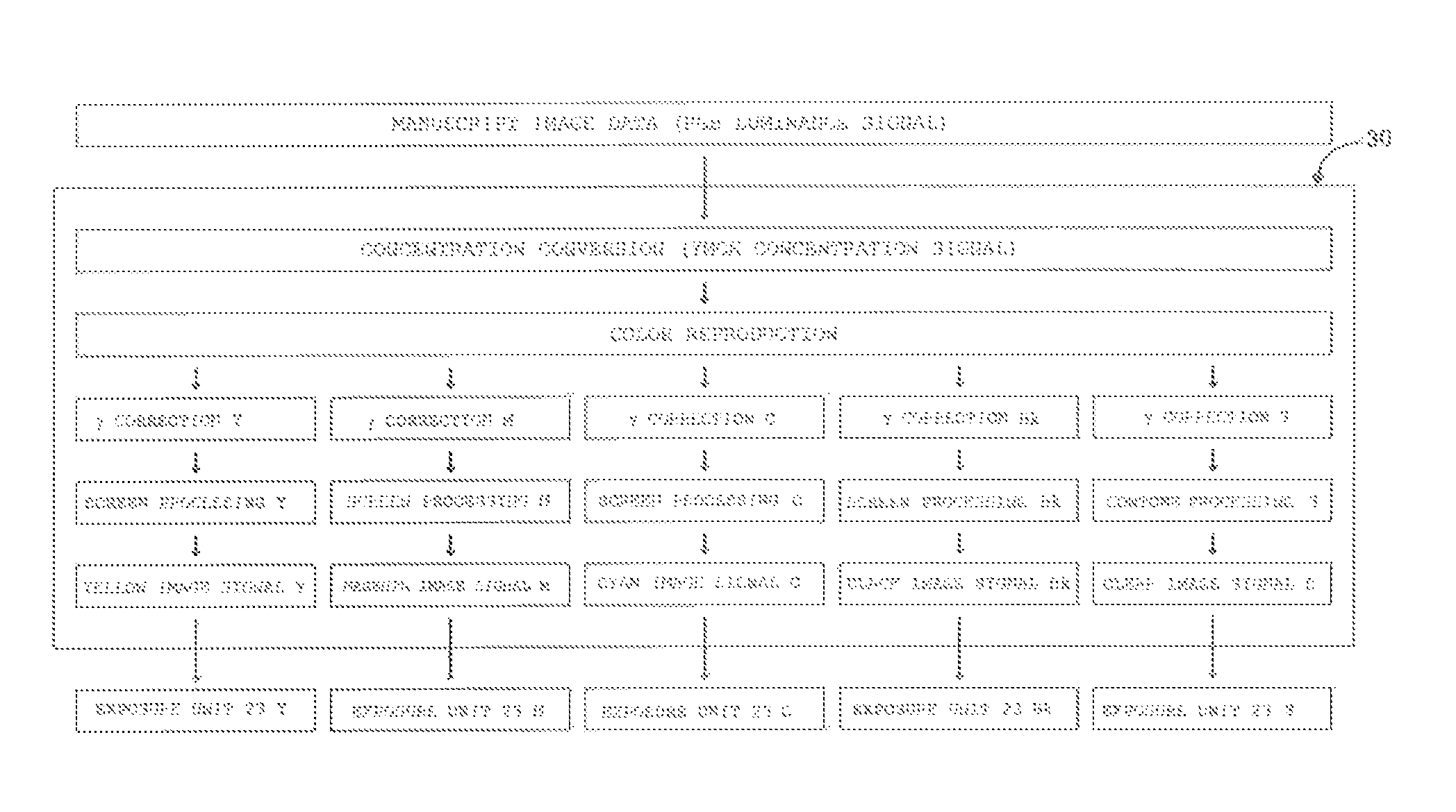
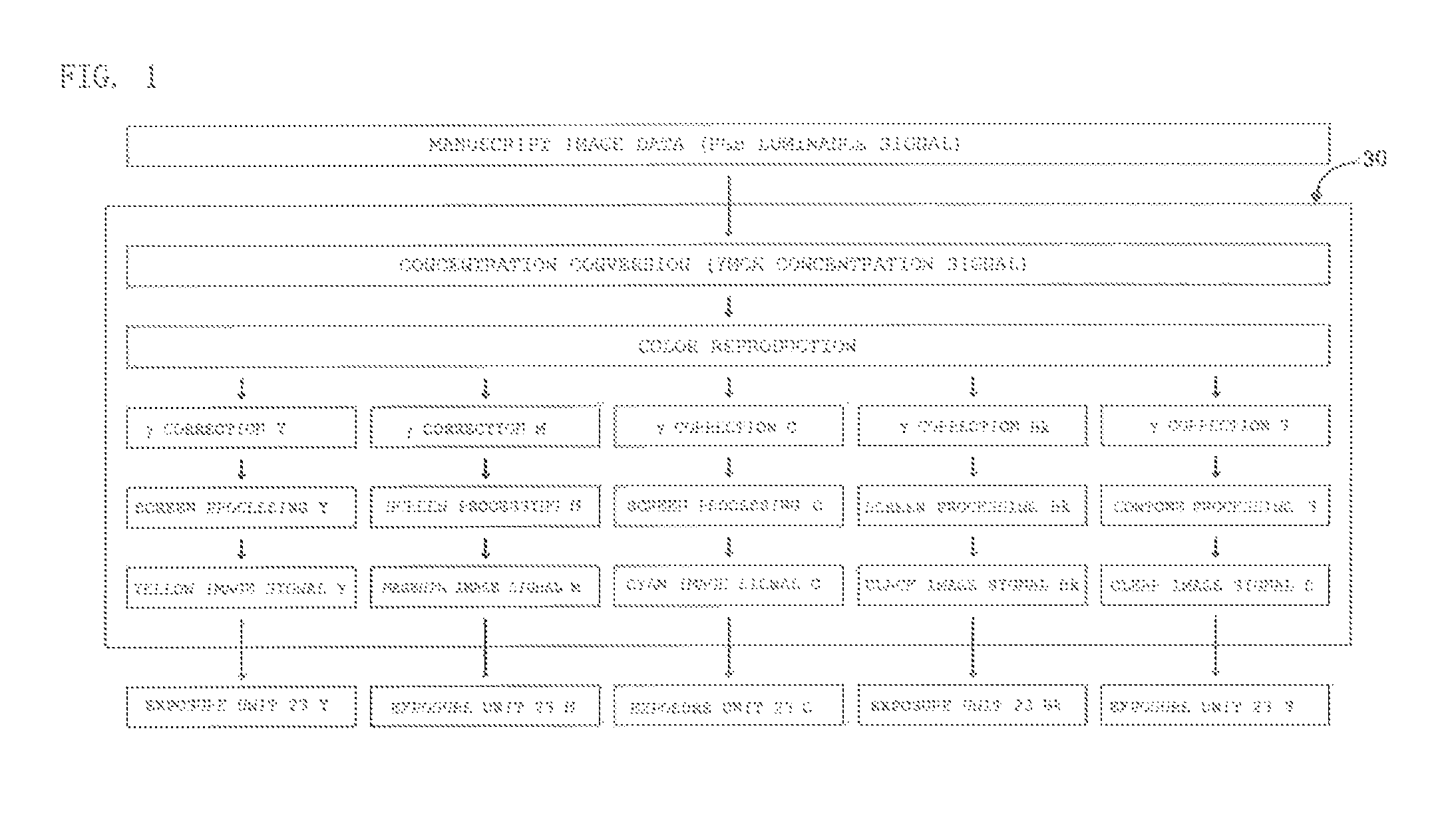
The present invention relates to an image forming method that prevents moiré and ensures sufficient color saturation and gloss. It does not use an excessive amount of clear toner and avoids deformation of the color toner image. The method uses a clear image signal obtained through the contone processing to form a clear toner image, which is then deposited on the color toner image. This controlled deposition results in a lower amount of color toner per unit area and a higher amount of clear toner, resulting in an image with sufficient gloss.

Problems solved by technology

However, there was the problem with the method disclosed in Patent Literatures 1 and 2 that in practice, a positional deviation tends so occur in the position of adhesion, of the clear toner because the resist is controlled with, difficulty, thereby causing the resulting image not to be smoothed and thus not to be glossy as intended.
There was also the problem with the method disclosed in Patent Literatures 3 and 4 chat in forming a toner image using a screen having a large number of lines, precise control has to be provided to the diameter of a laser beam used for exposure.
However, there is a limit to the preciseness of the control, and the use of the screen may result in degradation in image quality due to interference such as moire.

Method used


Image

  • Image forming method
  • Image forming method
  • Image forming method

Examples


example 1

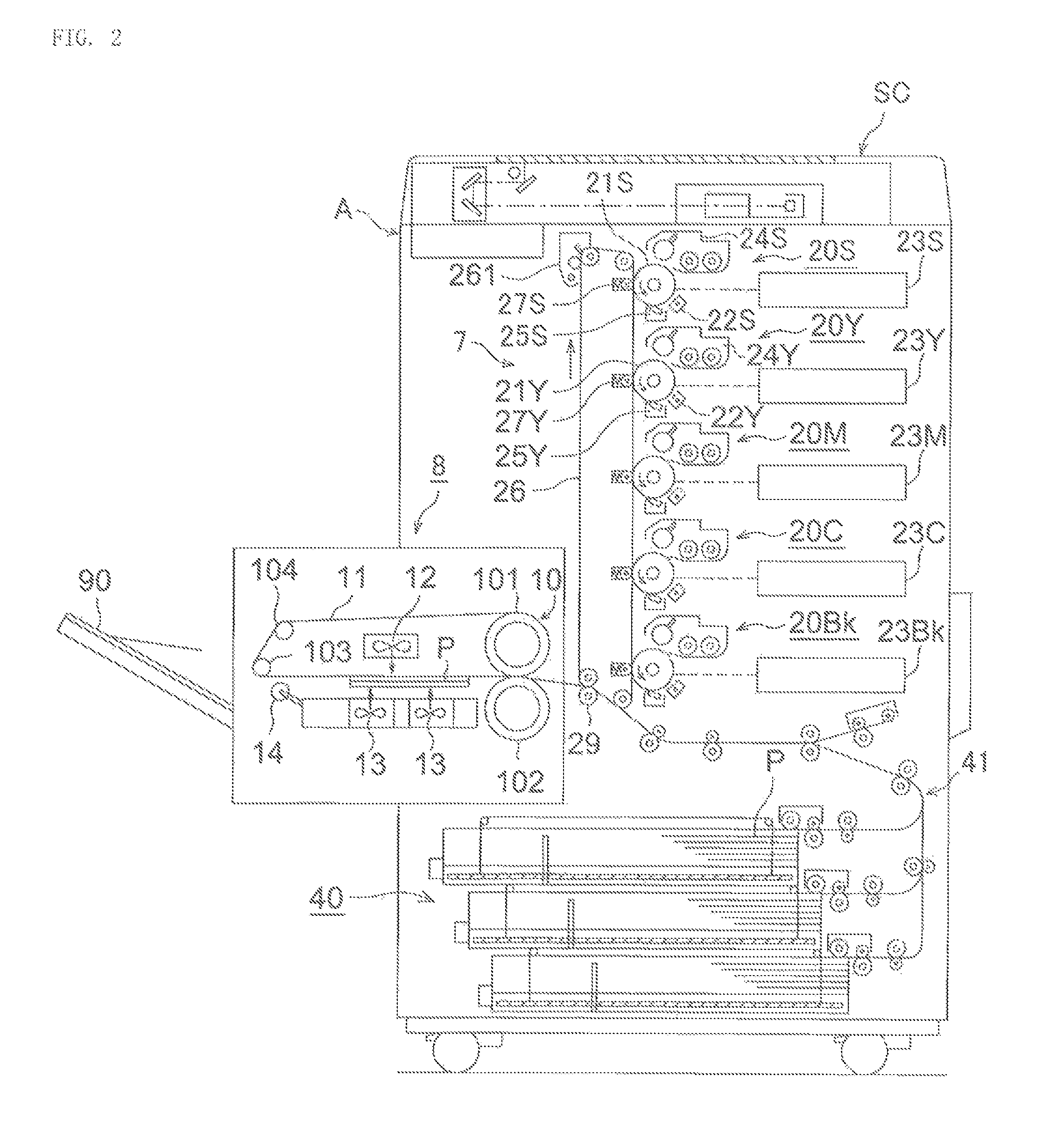
[0112]The image forming apparatus shown in FIG. 2 was used to form, on a sheet of ordinary paper, a test image [1] having image regions A to B with varying densities in magenta in one image as shown in FIG. 3(a). At this time, the magenta toner image was formed in accordance with a magenta image signal obtained through the screen processing using a dot screen pattern having a screen line count of 190 lpi. Furthermore, the clear toner image was formed in accordance with a clear image signal obtained through the contone processing. The clear image signal is assumed to have been controlled so that the total amount (the pre-set amount) of (the adhered magenta toner+the adhered clear toner) was 10 g / m2.

[0113]In the test image shown in FIG. 3(a), the numerical value in each image region indicates the amount of adhered magenta toner.

example 2

[0114]The image forming apparatus shown in FIG. 2 was used to form, on a sheet of ordinary paper, a test image [2] having image regions A to D with varying densities in magenta and cyan in one image as shown in FIG. 3(b). At this time, the magenta toner image and the cyan toner image were formed in accordance with a magenta image signal and a cyan image signal obtained through the screen processing using a dot screen pattern having a screen line count of 190 lpi. Furthermore, the clear toner image was formed in accordance with a clear image signal obtained through the contone processing. The clear image signal is assumed to have been controlled so that the total amount (the pre-set amount) of (the adhered magenta toner+the adhered cyan toner+the adhered clear toner) was 10 g / m2.

[0115]In the test image shown in FIG. 3(b), the upper numerical value in each image region indicates the amount of adhered magenta toner, while the lower numerical value indicates the amount of adhered cyan t...

example 3

[0116]A test image [3] was formed in the same manner as in Example 1 except that the magenta toner image was formed using a screen pattern having a screen line count of 270 lpi in Example 1.


PUM


Abstract

An image forming method which is capable of preventing occurrence of moire and forming images having sufficient color saturation and a sufficient gloss is provided. The color toner image is formed in accordance with a color image signal obtained through screen processing using a screen pattern having a screen line count of 50 to 270 lpi on manuscript image data, and the clear toner image is formed in accordance with a clear image signal obtained through contone processing on the manuscript image data. The clear image signal is controlled so that, according to the amount of the color toner per unit area of the stacked toner image obtained by the color toner image being superimposed with the clear toner image, the less the amount of the color toner, the more the amount of the clear toner becomes.

Description

CROSS REFERENCE TO RELATED APPLICATION[0001]This Application claims the priority of Japanese Patent Application No. 2013-061490 filed on Mar. 25, 2013, which is incorporated by reference herein.TECHNICAL FIELD[0002]The present invention relates to an image forming method which is capable of collectively fixing a color toner image and a clear toner image and then outputting a glossy image.BACKGROUND ART[0003]The image forcing apparatus of electrophotographic system, for example, a full-color image forming apparatus, provides output typically in a manner such that using toners of three colors, yellow, cyan, and magenta, or toners of four colors with black added to the three colors, dots of each color toner are to rood on an lavage support such as a sheet of papery thereby allowing a full-color image to be visually identified as a whole.[0004]In an electrophotographic system, halftone images can be formed, for example, according to data obtained by performing screen processing using a ...

Claims


Application Information

Patent Timeline
Patent Type & Authority Patents(United States)
IPC IPC(8): G06F3/12G03G15/00G03G15/01
CPCG03G15/6585G03G15/0189
Inventor YASUKAWA, HIROYUKINOMURA, SHOICHIMOGI, KENTAROUMATSUSHIMA, ASAO
Owner KONICA MINOLTA INC
Learn More