Resonator-enhanced optoelectronic devices and methods of making same

a technology of optoelectronic devices and phosphorescent materials, which is applied in the field of optoelectronic devices, can solve the problems of increasing the cost of phosphorescent materials, and the conventional use of phosphorescent materials has not solved the problem

Inactive Publication Date: 2015-04-28
VERLASE TECH
View PDF11 Cites 289 Cited by
  • Summary
  • Abstract
  • Description
  • Claims
  • Application Information

AI Technical Summary

Problems solved by technology

However, the quantity of such materials used in many of these devices and the increased complexity of some of these devices make them more expensive than desired.
In addition, conventional usage of phosphorescent materials has not solved problems that continue to exist, such as the green gap noted above.

Method used


Image

  • Resonator-enhanced optoelectronic devices and methods of making same
  • Resonator-enhanced optoelectronic devices and methods of making same
  • Resonator-enhanced optoelectronic devices and methods of making same

Examples


Embodiment Construction

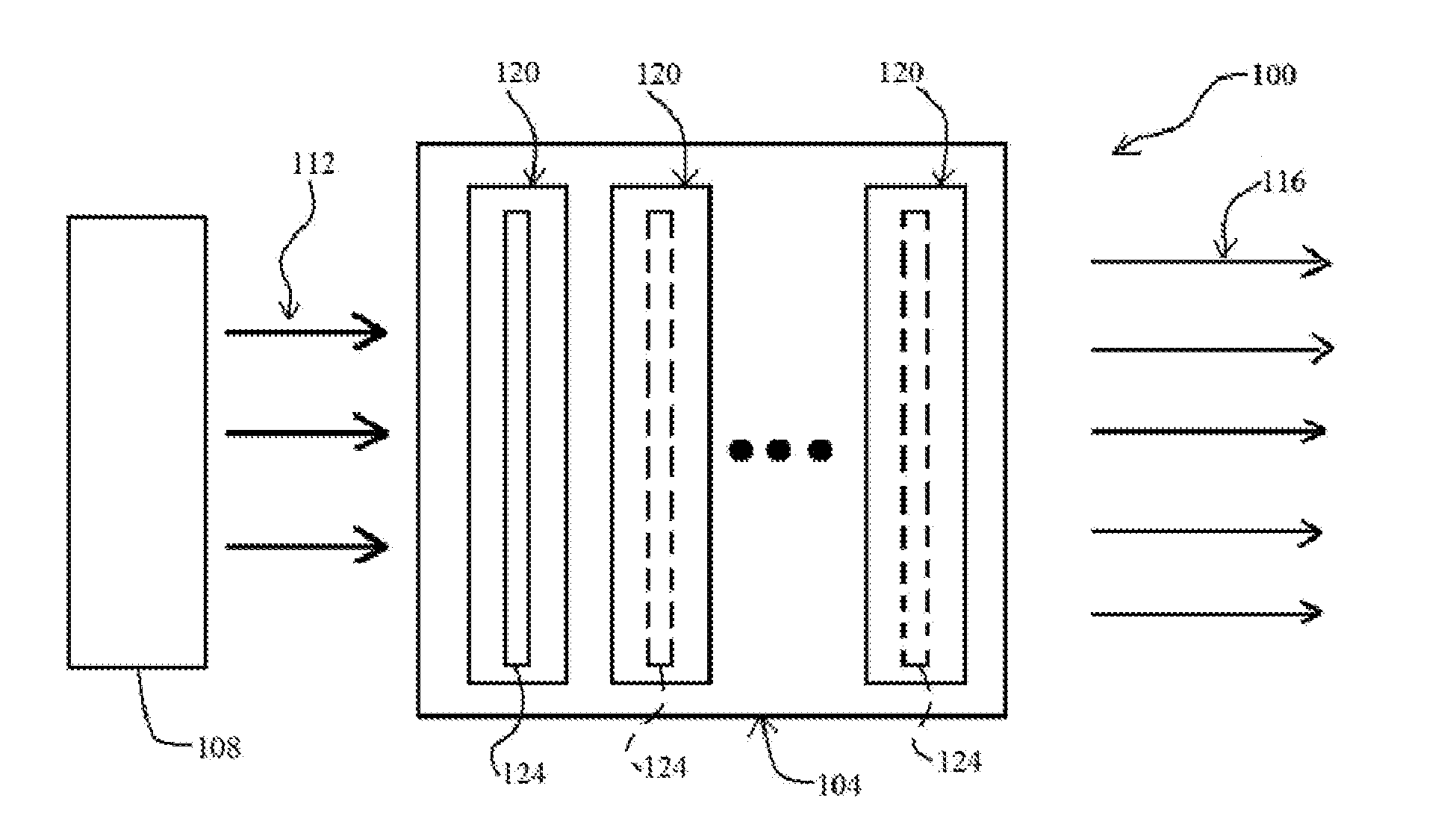
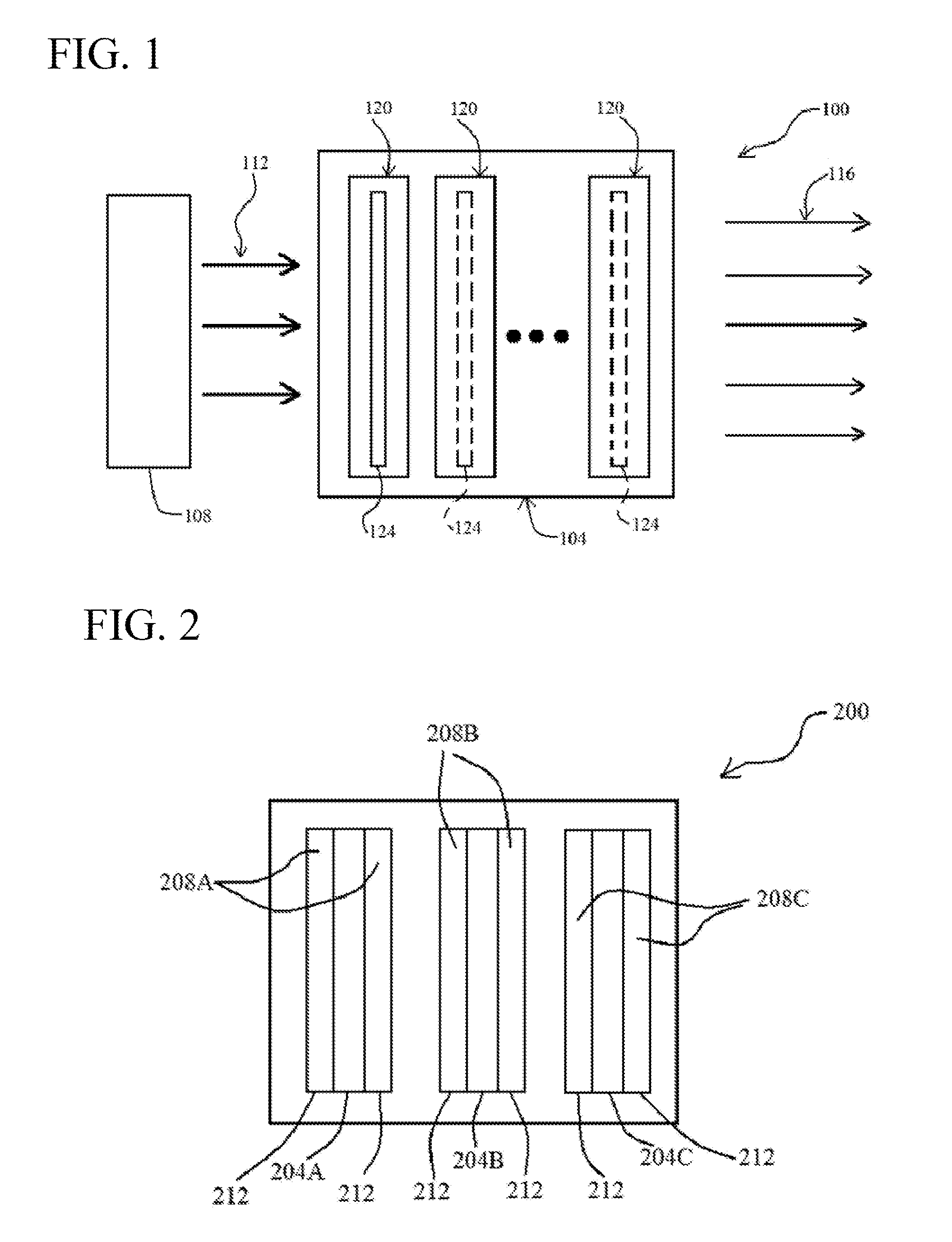
[0039]Referring now to FIG. 1, in one aspect the present invention is directed to a light-emitting system 100 that includes at least one optical resonator 104 (only one is shown for convenience; some of the examples below show multiple resonators) and at least one light source 108 that provides input light 112 to, or pumps, the optical resonator(s) and results in each optical resonator outputting output light 116. Unique features of optical resonator 104 include its having multiple optical resonator cavities 120 and at least one photoluminescent material 124. As will become evident from reading this entire disclosure, multiple optical resonator cavities 120 are typically located in series with one another, i.e., with each cavity being either adjacent to another cavity or between two cavities.

[0040]Photoluminescent material 124 can be composed of virtually any material that photoluminesces in the presence of input light 112 and that produces the desired effect. Photoluminescent mater...


PUM


Abstract

Optical resonators that are enhanced with photoluminescent phosphors and are designed and configured to output light at one or more wavelengths based on input / pump light, and systems and devices made with such resonators. In some embodiments, the resonators contain multiple optical resonator cavities in combination with one or more photoluminescent phosphor layers or other structures. In other embodiments, the resonators are designed to simultaneously resonate at the input / pump and output wavelengths. The photoluminescent phosphors can be any suitable photoluminescent material, including semiconductor and other materials in quantum-confining structures, such as quantum wells and quantum dots, among others.

Description

RELATED APPLICATION DATA[0001]This application claims the benefit of priority of: U.S. Provisional Patent Application Ser. No. 61 / 518,989, filed on May 16, 2011, and titled “New and Novel methods to increase the efficiency of Opto-electronic devices”; U.S. Provisional Patent Application Ser. No. 61 / 573,872, filed on Sep. 14, 2011, and titled “New and Novel methods to increase the efficiency of Opto-electronic devices”; Provisional Patent Application Ser. No. 61 / 628,955, filed on Nov. 10, 2011, and titled “New and Novel methods to increase the efficiency of Opto-electronic devices”; and Provisional Patent Application Ser. No. 61 / 631,135, filed on Dec. 29, 2011, and titled “New and Novel methods to increase the efficiency of Opto-electronic devices”. Each of the foregoing applications is incorporated by reference herein in its entirety.FIELD OF THE INVENTION[0002]The present invention generally relates to the field of optoelectronic devices. In particular, the present invention is dir...

Claims


Application Information

Patent Timeline
Patent Type & Authority Patents(United States)
IPC IPC(8): H01S5/30B82Y20/00H01L33/50H01S3/00H01S3/082H01S5/00H01S5/10
CPCH01S5/10H01S5/005H01S3/0092H01S3/082H01S5/1096H01S5/1092H01L33/502B82Y20/00Y10S977/755Y10S977/774H01S5/0087H01S3/05G02B5/20G02B5/207H01L31/02327H01L31/162
Inventor JAIN, AJAYKUMAR R.
Owner VERLASE TECH
Why Eureka
Try Eureka