
Apparatus and method for improving safety and quality of automatic riveting operations

a technology of automatic riveting and automatic riveting, which is applied in the direction of manufacturing tools, metal-working machine components, measurement/indication equipment, etc., can solve the problems of workpiece positioning error, affecting the automatic riveting machine may experience errors that affect quality, safety, or both quality and safety, so as to improve efficiency, quality and safety.

Inactive Publication Date: 2015-05-05
GEN ELECTRO MECHANICAL
View PDF10 Cites 14 Cited by
  • Summary
  • Abstract
  • Description
  • Claims
  • Application Information

AI Technical Summary

Benefits of technology

The invention is an improved automatic riveting apparatus that uses sensors to measure force and deflection during production. This allows for fine tuning of the motion of the tool and adjustment of the clamping force and workpiece position. This improves efficiency, quality, and safety during production.

Problems solved by technology

During operation, automatic riveting machines may experience errors that affect quality, safety, or both quality and safety.
One type of error is a workpiece positioning error.
The difference in weight and how the test coupon is held compared to the fixtured production panel may introduce positioning errors when running the production panels.
As another example, if there is error in the panel position, the anvil will not be in the correct position to contact the fastener which can create panel distortion during the fastening process.
The anvil will also not seat an interference fit fastener properly if the panel is not in the correct position.
Positioning errors of the kinds mentioned above often result in poor quality in the end product, and can lead to scrapping of expensive panels.
In extreme cases, operator injury may result.
Another type of error is insufficient clamping force.
This can lead to dangerous conditions.
For example, when running set up operations on coupons, an unclamped or under-clamped coupon can spin during the drilling operation and potentially injure personnel.
It is also known to have errors in the automatic fastening process related to other factors.
For example, a foreign object may become lodged between the pressure foot bushing and the panel surface.
As another example, the drill bit used for drilling operations or the cutter used for shaving operations may become dull or break, and this will have a negative impact on quality.
Manual measurement slows down execution, and the operator observation is not always reliable.
Often, program execution is halted after it is too late to save the panel or prevent injury.

Method used


Image

  • Apparatus and method for improving safety and quality of automatic riveting operations
  • Apparatus and method for improving safety and quality of automatic riveting operations
  • Apparatus and method for improving safety and quality of automatic riveting operations

Examples


first embodiment

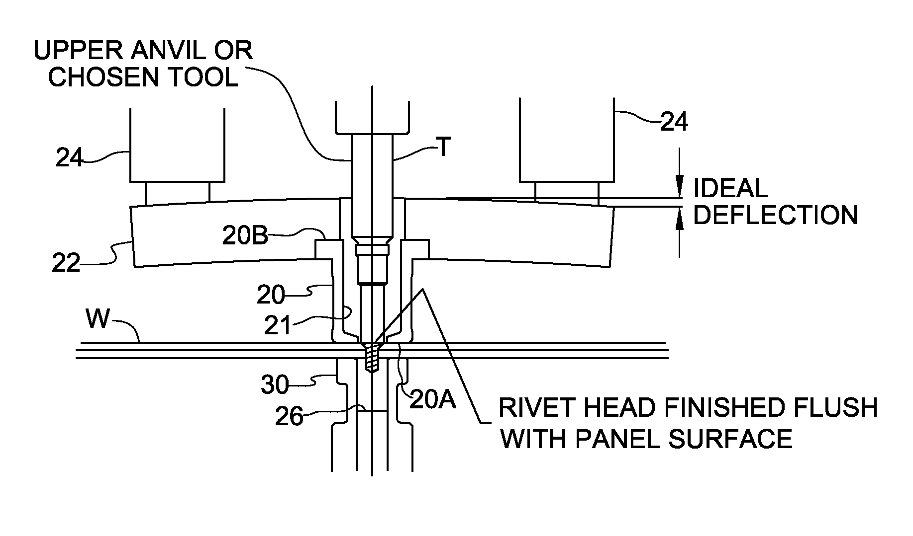
[0048]In accordance with the present invention, at least one sensor 50 is connected to pressure foot plate 22 for generating a respective sensor signal indicative of force transmitted between the pressure foot plate 22 and the pressure foot bushing 20. In a first embodiment shown in FIGS. 11A and 11B, the at least one sensor 50 is a pair of strain gauges 50 affixed to an undersurface 22A of pressure foot plate 22. As best seen in FIG. 11B, strain gauges 50 may be arranged parallel to one another and symmetrically about tool axis 15. As will be understood, strain gauges 50 measure deflection of pressure foot plate 22 and provide respective signals having an amplitude proportional to force transmitted between the pressure foot plate 22 and the pressure foot bushing 20. The signals may be combined to provide a single output signal, or kept separate. It is also possible to use only one strain gauge 50, or more than two strain gauges 50. A strain gauge having a deflection capacity of 0.0...

second embodiment

[0050]FIGS. 12A and 12B show a second embodiment wherein the at least one sensor 50 includes a ring-shaped load cell arranged between an inner shoulder 22B of pressure foot plate 22 and the supported end 20B of pressure foot bushing 20. Load cell 50 should be chosen to allow sufficient Z-axis travel of the pressure foot plate 22 relative to pressure foot bushing 20 under maximum anticipated loading to prevent the load cell from “bottoming out”.

[0051]FIGS. 13A and 13B show a third embodiment wherein the at least one sensor 50 includes a plurality of individual load cells arranged in an angular array about tool axis 15 between inner shoulder 22B of pressure foot plate 22 and supported end 20B of pressure foot bushing 20. Load cells 50 are preferably arranged at regular angular intervals about tool axis 15 and at a common radial distance from the tool axis. The embodiment depicted in FIGS. 13A and 13B has three load cells arranged at 120-degree intervals, however more than three load c...


PUM

PropertyMeasurementUnit
temperatureaaaaaaaaaa
resistanceaaaaaaaaaa
clamping forceaaaaaaaaaa

Abstract

An automatic riveting apparatus is improved by providing at least one sensor on a pressure foot plate or at an interface between the pressure foot plate and a pressure foot bushing of the apparatus for generating a signal indicative of force transmitted between the pressure foot plate and the pressure foot bushing. For example, the at least one sensor may include a strain gauge or other type of sensor for measuring deflection of the pressure foot plate, or it may include load cell(s) for measuring force at the interface between the pressure foot plate and the pressure foot bushing. A control system of the apparatus may be configured to execute one or more control functions based on a value of the sensor signal or signals. The control functions may adjust machine operation commands or trigger a safety mode based at least in part on the sensor signal.

Description

FIELD OF THE INVENTION[0001]The present invention relates to the field of automatic riveting machines and automatic riveting methods.BACKGROUND OF THE INVENTION[0002]Automatic riveting machines are used in connection with fabricating the components of aircraft, for example the wing and fuselage portions of the aircraft. The machines are capable performing tooling operations on a workpiece, for example a panel or stack of panels. The operations typically include drilling and countersinking holes, positioning rivet slugs in the drilled holes, upsetting the rivet slugs to form an enlarged head at one end or a pair of enlarged heads at opposite ends of the slug, and shaving each rivet head such that it is substantially flush with the surface of the workpiece.[0003]In order to perform the various operations necessary to install a rivet, an automatic riveting machine may comprise a head assembly locatable relative to the workpiece at respective rivet installation positions. In one configu...

Claims


Application Information

Patent Timeline
Patent Type & Authority Patents(United States)
IPC IPC(8): B21J15/04B23Q17/00
CPCB23Q17/005B21J15/02B21J15/142Y10T29/49776
Inventor BURNS, THOMAS E.KUBANEK, KURT R.RUMMELL, THOMAS H.BEAM, MICHAEL M.
Owner GEN ELECTRO MECHANICAL
Learn More