
Ground surface reconnaissance projectile

Active Publication Date: 2015-05-05
UNITED STATES OF AMERICA THE AS REPRESENTED BY THE SEC OF THE ARMY
View PDF3 Cites 5 Cited by
  • Summary
  • Abstract
  • Description
  • Claims
  • Application Information

AI Technical Summary

Benefits of technology

This patent describes a new kind of weapon that can be used from a long way back. It has a lot of different sensors and can automatically identify targets of interest. It's like a high-end surveillance system that can be placed remotely. This new weapon is a 60 mm mortar that can keep track of things while being fired at and can send back information about what it's seeing.

Problems solved by technology

Such delivery methods, while efficient for larger reconnaissance devices, may prove to be not feasible or inordinately costly and inaccurate to certain extent, particularly for distributing smaller reconnaissance devices over the target location within an enemy territory, or over a terrain that may be too difficult to reach by foot, such as in a mountainous region.
The need for such a reconnaissance projectile has heretofore remained unsatisfied.

Method used


Image

  • Ground surface reconnaissance projectile
  • Ground surface reconnaissance projectile
  • Ground surface reconnaissance projectile

Examples


Embodiment Construction

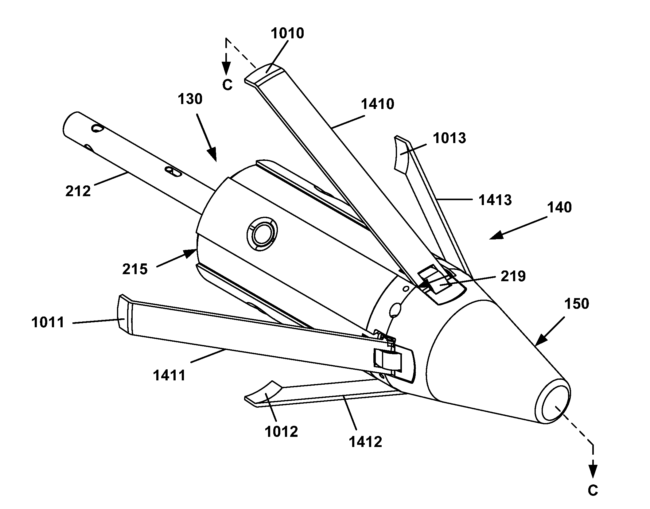
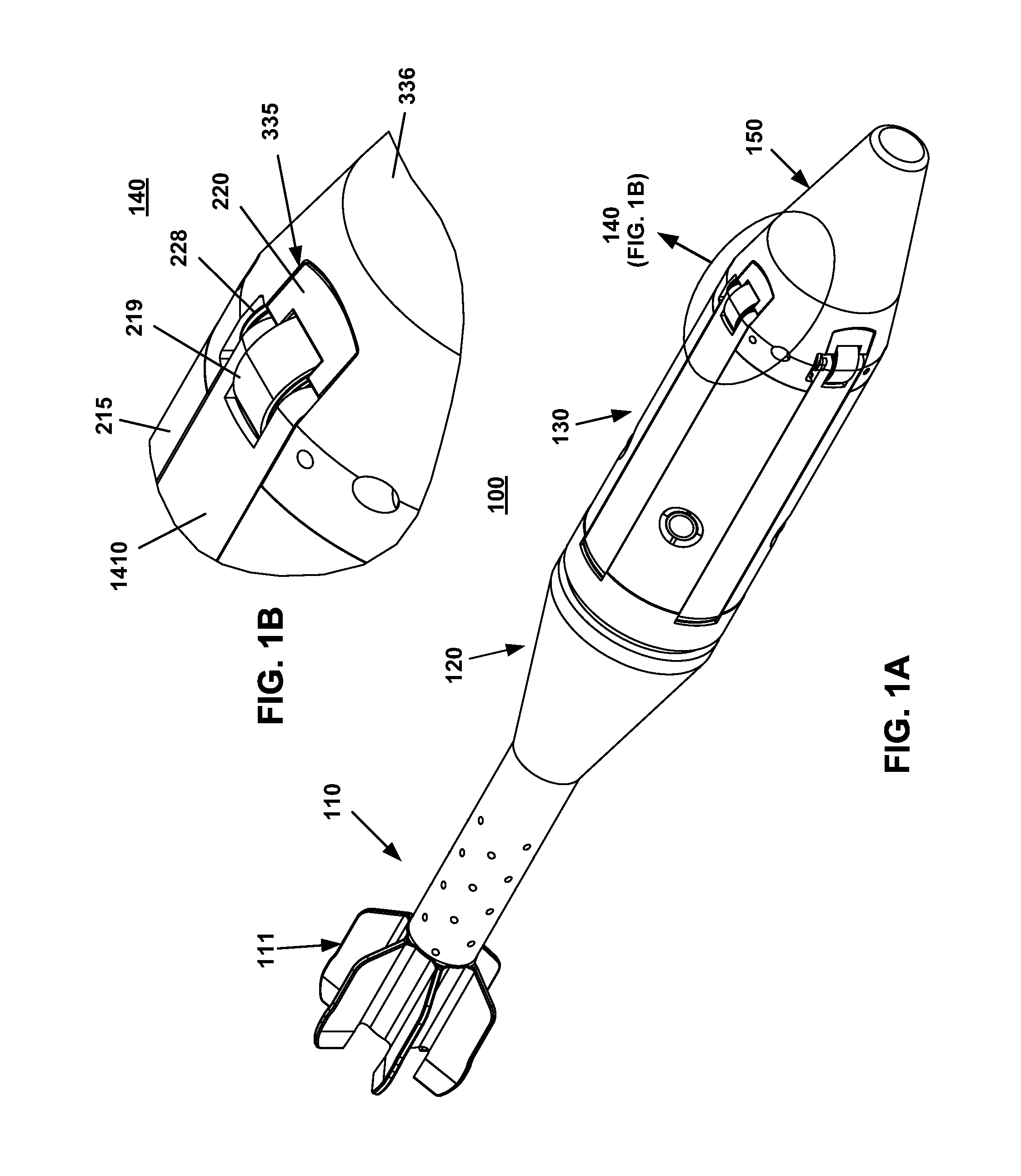
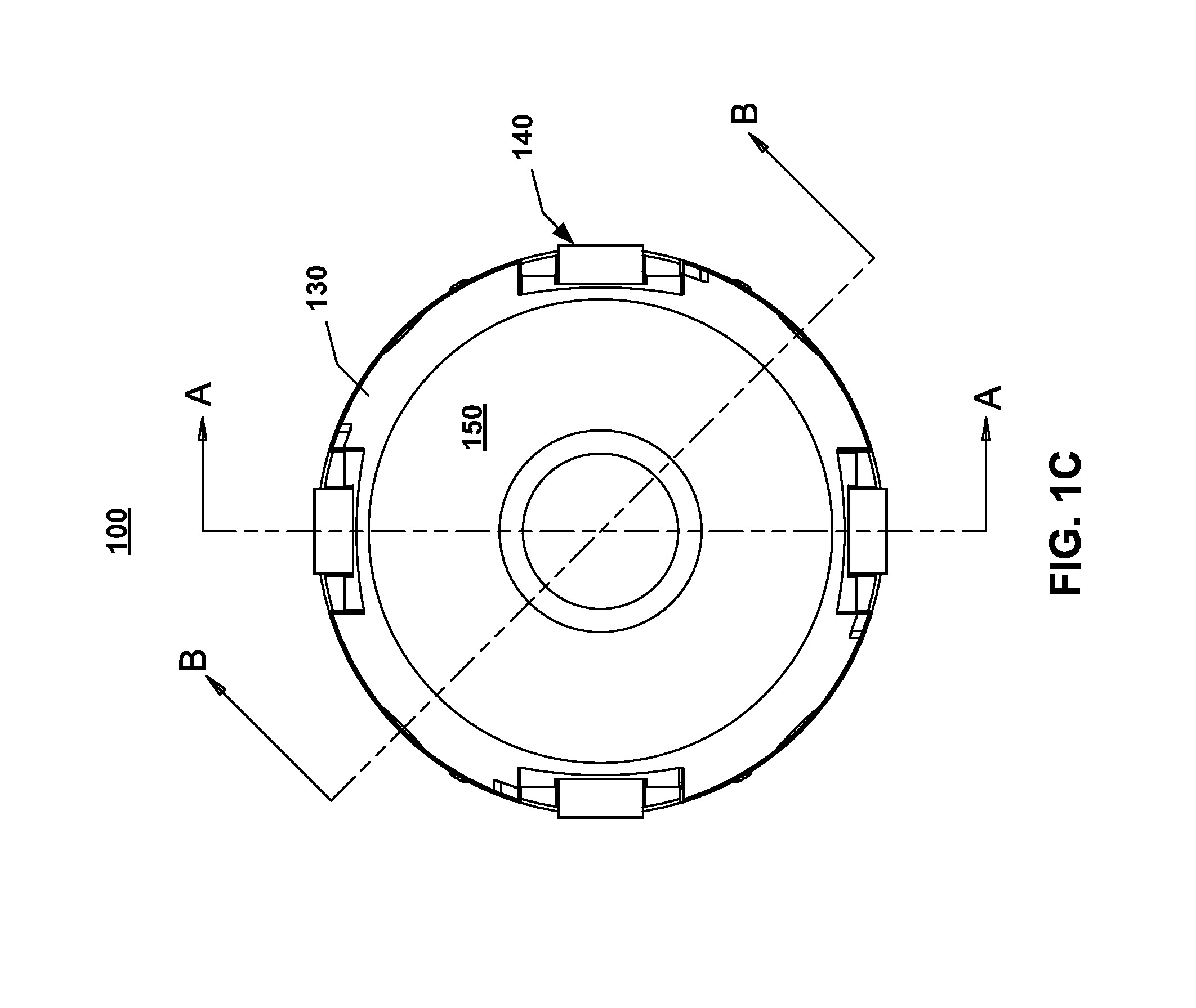
[0028]With reference to FIGS. 1A and 1C, the present invention provides a ground reconnaissance device, such as a reconnaissance projectile 100 that is capable of performing ground level Intelligence, reconnaissance and surveillance (ISR) for an extended period of time after the projectile 100 has landed. The projectile 100 generally includes a plurality of interconnected sections: a fail boom 110, a rear body 120, a main body 130, four leg hinge assemblies 140, 141, 142, 143, and a nose cone 150.

[0029]The tail boom 110 generally includes a plurality of fins 111, as is known in the field. As a result, the tail boom 110 will not be described in greater detail. Similarly, the nose cone 150 is known in the field and will not be described herein in detail. The outer shape of the nose cone 150 is selected to maintain standard aerodynamic properties.

[0030]According to a preferred embodiment of the present invention, the projectile 100 is a 60 mm custom inert mortar projectile whose rear b...


PUM


Abstract

A ground surface reconnaissance projectile includes a tube-launched 60 mm inert mortar round, which remotely relays reconnaissance and surveillance data back to an operator, after it has landed and uprighted itself. The types of collected data include for example, visual imagery of the target area in 360 degrees, acoustic target tracking and voice recognition, infra-red motion detection, and magnetic field disturbance sensing.

Description

GOVERNMENTAL INTEREST[0001]The invention described herein may be manufactured and used by, or for the Government of the United States for governmental purposes without the payment of any royalties thereon.FIELD OF THE INVENTION[0002]The present invention relates to the field of ground sensors, and it more particularly relates to a ground surface reconnaissance projectile which is aerially deployable to a target location.BACKGROUND OF THE INVENTION[0003]Reconnaissance projectiles, including unattended ground sensors (UGS), have been developed for military use to satisfy the persistent need for reconnaissance, particularly in war situations. An exemplary need is for the prolonged deployment of the reconnaissance projectiles, while maintaining the survivability of the electronic components and sensors housed within the reconnaissance projectiles.[0004]As used herein, a reconnaissance projectile is an unmanned monitoring platform that is often used for various military activities, such ...

Claims


Application Information

Patent Timeline
IPC IPC(8): F42B5/08F41H13/00F42B12/02F42B30/10
CPCF42B12/02F42B30/10F41H13/00F42B5/08F42B12/365
Inventor STOFKO, PAVOLCARLUCCI, PASQUALEMELLINI, MARKMOUGEOTTE, CHRISTOPHER
Owner UNITED STATES OF AMERICA THE AS REPRESENTED BY THE SEC OF THE ARMY
Learn More