Rotor

a technology for electric motors and rotors, which is applied in the direction of stator/rotor bodies, magnetic circuit rotating parts, magnetic circuit shape/form/construction, etc. it can solve the problems of difficult and therefore costly process, difficult to hold the permanent magnet elements exactly in position during injection molding operation, etc., to achieve high resistance and position stability securing, increase the efficiency of electric motors and therefore performance, and cost-effective production

Active Publication Date: 2015-05-05
VITESCO TECH GERMANY GMBH
View PDF23 Cites 4 Cited by
  • Summary
  • Abstract
  • Description
  • Claims
  • Application Information

AI Technical Summary

Benefits of technology

[0007]Since the basic body is surrounded partially by a joining sleeve which has chamber walls, the chamber walls forming with the bearing surfaces at least one chamber in which the at least one permanent-magnetic element is arranged, the at least one permanent-magnetic element is held very exactly in position on the bearing surfaces. This gives rise to a very well-balanced rotor which has no unbalance, even when running at high speed, and therefore subjects the rotor bearing to only slight load. This contributes considerably to a long service life of the electric motor. Since the joining sleeve fixes the permanent-magnetic element in position on the basic body in the radial direction, a shift of the permanent-magnetic element during injection molding and also after the production of the rotor is prevented in the radial direction. Since a locking element is injection-molded onto the basic body and closes the chamber and consequently fixes the permanent-magnetic element in position on the rotor in the axial direction, a high-quality rotor for an electric motor can be produced cost-effectively.
[0008]In one embodiment, the basic body has formed on it at least one channel which extends in the axial direction over the entire basic body that separates two bearing surfaces from one another, a chamber wall of the joining sleeve engaging into the channel. The engagement of the chamber wall into the channel advantageously secures the joining sleeve against twisting on the basic body.
[0009]If the channel has an undercut and an anchor element is formed on the chamber wall, the anchor element engages positively into the undercut a highly resistant and positionally stable securing of the joining sleeve to the basic body is ensured.
[0010]Since the basic body has formed on it a multiplicity of channels that separate a multiplicity of bearing surfaces from one another, and the joining sleeve has formed on it a corresponding multiplicity of chamber walls, every second one of which has an anchor element which engages positively into the undercut of an assigned channel, on the one hand, highly stable fixing of the joining sleeve and therefore of the permanent-magnetic elements on the basic body is achieved and, on the other hand, incompletely filled channels in the basic body remain, through which some of the mass of injection material can pass when the locking element is being injection-molded, with the result that the locking element can be formed on both end faces of the basic body, even if the mass of injection material is injection-molded onto only one end face. During injection molding, the liquid mass of injection material is pressed from the injection-molded end face of the basic body through the incompletely filled channels in the basic body onto the side lying opposite the injection-molded side of the basic body. In this case, the channels incompletely filled before injection molding are also filled completely with the mass of injection material.
[0011]In one embodiment, the basic body comprises a magnetically conductive material. For example, ferrometallic materials are suitable for this purpose, but materials comprising plastic-bound ferrometallic particles may also be used. The basic body comprising magnetically conductive material increases the efficiency of the electric motor and therefore also its performance. It is especially advantageous if the basic body is a bundle of punched sheet-metal parts.
[0012]The object is achieved, moreover, by a method for producing a rotor for an electric motor, the rotor having a basic body on which is formed at least one bearing surface. At least one permanent-magnetic element is attached to the bearing surface and is held solely by a holding tool, after which a joining sleeve with chamber walls is pushed on in the axial direction over the basic body and the permanent-magnetic element. The permanent-magnetic element is therefore then held by the joining sleeve and the holding tool can be removed. This ensures that the permanent-magnetic element is fixed to the basic body sufficiently in the radial direction by the joining sleeve and the bearing surface. The joining sleeve is then pushed completely over the permanent-magnetic element and a locking element is injection-molded onto the basic body by the injection molding method. The locking element causes the permanent-magnetic element to be fixed to the basic body in the axial direction. The method disclosed here is very simple and cost-effective, since complicated processes, such as gluing or welding, can be dispensed with entirely. The joining sleeve can be produced in a separate injection molding process, before the mounting of the rotor, in a highly cost-effective way and with high accuracy. The method presented here for producing a rotor is suitable especially for the fully automatic production of the rotor. This saves production costs and minimizes the error rate.

Problems solved by technology

In this case, however, it is very difficult to hold the permanent-magnetic elements exactly in position during the injection molding operation.
This, however, is a very difficult and therefore costly process which also often leads to insufficient results.

Method used


Image

  • Rotor
  • Rotor
  • Rotor

Examples


Embodiment Construction

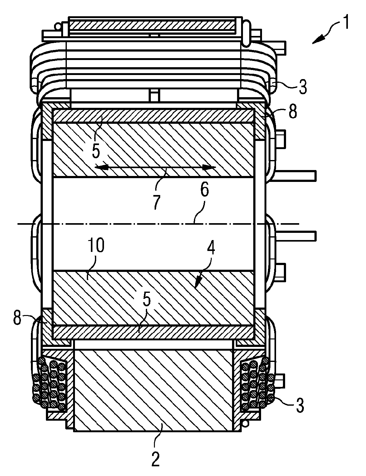
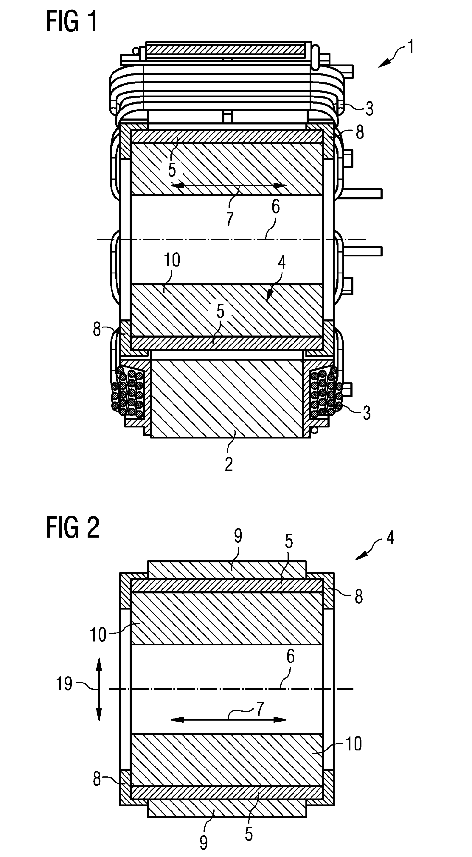
[0023]FIG. 1 shows an electric motor 1 with a stator 2 and with a rotor 4. Electric motor 1 may be a reluctance motor, as it is known. Coils 3 are attached to the stator 2 and can be subjected to a commutated electrical current whereby a magnetic alternating field can be generated. The rotor 4 is mounted rotatably on an axis 6 and has a basic body 10 and permanent-magnetic elements 5. These permanent-magnetic elements 5 are held on the basic body 10 by a joining sleeve 9 and a locking element 8 (FIG. 2). The arrow indicates the axial direction 7 in which, for example, the joining sleeve 9 can be pushed onto the basic body 10. The permanent-magnetic elements 5 are of parallelepipedal form, this being especially cost-effective. However, they may also be of shell-shaped form.

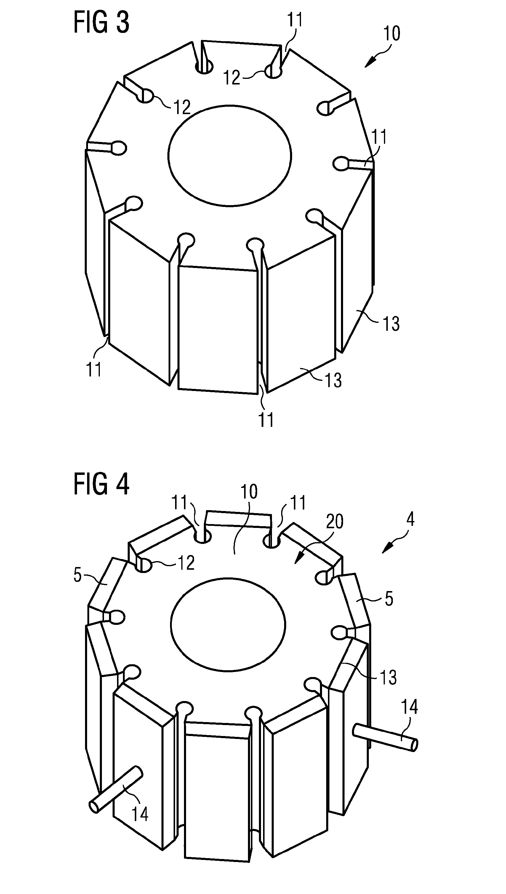
[0024]The set-up of the rotor 4 is illustrated in more detail in FIG. 2. A multiplicity of permanent-magnetic elements 5, which are arranged on the cylindrical outer surface of the basic body 10, are shown. The per...


PUM


Abstract

A rotor for an electric motor that includes a main body on which a support surface is formed, to which a permanent magnet element is attached. The main body is partially surrounded by a joining sleeve having chamber walls. The chamber walls together with the support surfaces form a chamber in which the permanent magnet element is arranged. The joining sleeve fixes the position of the permanent magnet element in a radial direction on the main body and a locking element is molded onto the main body. The locking element closes the chamber fixing the position of the permanent magnet element in the axial direction on the main body.

Description

CROSS REFERENCE TO RELATED APPLICATIONS[0001]This is a U.S. national stage of application No. PCT / EP2011 / 055389, filed on 7 Apr. 2011. Priority is claimed on German Application No. 10 2010 014 597.1 filed 9 Apr. 2010, the content of which is incorporated here by reference.BACKGROUND OF THE INVENTION[0002]1. Field of the Invention[0003]The invention relates to a rotor for an electric motor, the rotor having a basic body on which is formed at least one bearing surface, to which at least one permanent-magnetic element is attached. The invention relates, furthermore, to a method for producing a rotor for an electric motor.[0004]2. Description of the Prior Art[0005]Rotors for electric motors of the type initially mentioned are known and are used in many different ways. There are different methods for fastening the permanent-magnetic elements to the basic body of the rotor. It is known, for example from DE 10 2005 052 870 A1, to inject a plastic completely around the permanent-magnetic el...

Claims


Application Information

Patent Timeline
Patent Type & Authority Patents(United States)
IPC IPC(8): H02K21/12H02K1/27H02K15/03
CPCH02K1/278H02K15/03H02K1/28H02K1/02
Inventor BRANDAU, RUDIGERSIEBALD, KURT
Owner VITESCO TECH GERMANY GMBH
Why Eureka
Try Eureka