Beer dispensing device and system

a technology for dispensing devices and beverages, applied in the direction of liquid dispensing, liquid transferring devices, packaging, etc., can solve the problems of high energy consumption, difficult to transport, set up or break down, and large system space requirements, so as to reduce the amount of space required, convenient pouring height, and safe and visible neat beer dispensing area

Active Publication Date: 2015-05-12
WATTS LARZ
View PDF23 Cites 3 Cited by
  • Summary
  • Abstract
  • Description
  • Claims
  • Application Information

AI Technical Summary

Benefits of technology

[0028]A major advantage of the present invention is provided by the arrangement of its component parts. For example, in one embodiment, the housing component, which includes at least one beer line and beer coil, chills the beer, and has at least one beer faucet is situated above the keg and, thus, significantly reduces the amount of space required by conventional beer dispensing devices and systems that require keg cooling. Additional advantages are provided by the consolidation of the beer line(s) and coil(s) within the housing component as this arrangement of parts reduces extra lines typically hanging about the keg and conventional beer dispensing devices.
[0029]The housing component of the present invention is filled with cooling agents to chill beer after it leaves the keg and before it is dispensed. The housing component may contain cooling agents, such as ice and water, or any other suitable cooling agent, in various ratios. For example, the housing component may contain ice and water in ratios of about 80:20, 70:30, 60:40, 50:50, 40:60, 30:70, 20:80, 10:90, 5:95, etc. However, an optimal ratio of ice to water would be between about 70:30 ice to water and 30:70 ice to water, more preferable is a ratio of ice to water between about 60:40 ice to water and 40:60 ice to water, and most preferable is a ratio of about 50:50 ice to water. Of course it is understood that the precise ratio of ice to water is subject to change as ice melts. A desirable ratio of ice to water, or other cooling agent, can be maintained in the housing component, for example, by opening a drain plug in the base of the housing component to remove water. For example, water and / or ice can be added to the housing component via the top opening of the housing component during the use of the present invention to adjust the ratios of cooling agents used and / or to replace cooling agent(s) that have been removed. The drain plug may be of any type, including a threaded screw, a pull plug, and / or any similar type of instrument.
[0030]Generally, most domestic and mainstream lager style beers can be optimally used with the present invention when the keg has a starting temperature of between about 33 and about 55 degrees. Meanwhile, craft style micro-brew beers typically can be optimally used with the present invention when the keg has a starting temperature of between about 34 and about 42 degrees. When a keg of beer having a suitable starting temperature is connected to the present invention, and the use of cooling agents in the housing component is monitored, the present invention provides a steady flow of suitably chilled, fresh, foam free beer as it is dispensed, even if the keg itself warms while the present invention is being used.
[0031]In a preferred embodiment, the present invention is rested directly on top of a beer keg and optimally provides a convenient pouring height for chilled beer via beer faucet placed near the top of the housing component.
[0032]Optionally, however, the present invention may be placed on top of a table or other presentation, dispensing and / or serving surface. The beer line that runs from the housing component may be extended and run to the keg coupler on the keg that may be placed under the table or elsewhere. This will allow the use of a table or other surface for dispensing beer alongside promotional items, etc. Use of the present invention results in a safer and visibly neat beer dispensing area. A person serving beer using the present invention may also, beneficially, face others while dispensing beer to create a more social and less awkward exchange.
[0033]The beer faucet is preferably located near the top of the housing component to facilitate pouring beer from a more convenient height. For example, a beer faucet may be placed within about 8 inches of the top edge of the housing component. Preferably, the beer faucet is located within about one inch to six inches of the top edge of the housing component. More preferably, the beer faucet is located within about two inches to four inches of the top edge of the housing component. Most preferably, the beer faucet is located within about three inches of the top edge of the housing component.

Problems solved by technology

While such commercial systems advantageously use CO2 dispensing systems to prevent air from contacting the beer in the keg to keep the beer fresh for a longer period, such systems are expensive, large, heavy, energy-intensive, not easily transported, set up or broken down, and can be awkward and cumbersome to implement.
It is not practical or suitable to utilize this first type of beer dispensing system for temporary events or social gatherings.
Conventional consumer systems do not keep the beer in the keg fresh because oxygen in the air can quickly flatten the beer.
Heavy pressure bottles of compressed CO2 gas, such as those used in the commercial systems to keep beer fresh for a longer period of time, are not easily adapted to such consumer systems.
Furthermore, the beer keg associated with these consumer systems often inconveniently and inefficiently requires that the entire keg be chilled or iced down before and during the dispensing of beer.
Problematically, however, the beer lines attached to the keg are often outside of these cooling containers such that the beer in these lines is subject to undesirable warming.
External beer lines attached to kegs in cooling containers also present a safety hazard as they can fall off and / or become disconnected when people step on, kick, and / or trip over the external beer lines as they travel to, from, and around the keg.
The cooling containers themselves are large, often unattractive, and typically sit on the ground or on a table.
Furthermore, cooling containers can become very heavy when full and often inconveniently involve the need to dump out large amounts of water and ice during and / or after use.
A typical jockey box set up is a space consuming arrangement of separate parts.
If the cooler rests on the ground, then the beer dispensing faucet(s) will be approximately 8 inches to 1 inch from the ground, thus frustrating access to the beer faucet and requiring that the user bend over almost completely to the ground to pour beer.
The set up and break down of a jockey box requires great effort and is undesirably laborious.
For example, due to the amount of space required to mount the jockey box arrangement and size of its several parts, transportation of such a device requires a truck or a car with plenty of back seat and / or trunk space.
While it is possible to use a hand truck or dolly to transport the other box components (in addition to the keg or kegs), such as the cooler, table, or CO2 tank, etc., doing so is not recommended because the unbalanced nature of the hand truck or dolly will result in the parts being unbalanced and unsecured and could result in broken faucets or, falling or crushing hazards or, if the CO2 regulator is damaged or broken off, can result in a dangerous projectile that can result in serious injury or death.
Due to the many separate, large, heavy and / or cumbersome parts involved in setting up a jockey box, several time consuming, tiring, inconvenient, and possibly unsafe trips between the transport vehicle used to deliver the jockey box to a site and any set up location removed from the transport vehicle, such as a field, park, event space, etc., are required.
These beer and CO2 lines create unsafe tripping hazards and, because they are out in the open, often obtains abrasions and holes resulting in leaking beer and ultimately a foamy pour and messy beer serving area.
Furthermore, beer contained in the beer lines is exposed to potentially higher temperatures which can disadvantageously result in warm beer.
Use of bronco pumps results in wasted and un-drinkable beer.
Bronco pumps are also labor intensive and difficult to use.
Bronco pumps often dispense flat unsavory beer due to the introduction of regular air into the keg.
When regular air is pumped into the keg, it immediately begins to reduce the carbonation in the beer degrading its quality, and typically causes the beer to go flat within about 24 hours.
If only a portion of the keg is consumed, any remaining beer, once it has gone flat, is discarded, resulting in unnecessary waste.
Kegerators, however, are very expensive, cumbersome, require a power source, and not easily transportable for use at temporary events and functions.

Method used


Image

  • Beer dispensing device and system
  • Beer dispensing device and system
  • Beer dispensing device and system

Examples


Embodiment Construction

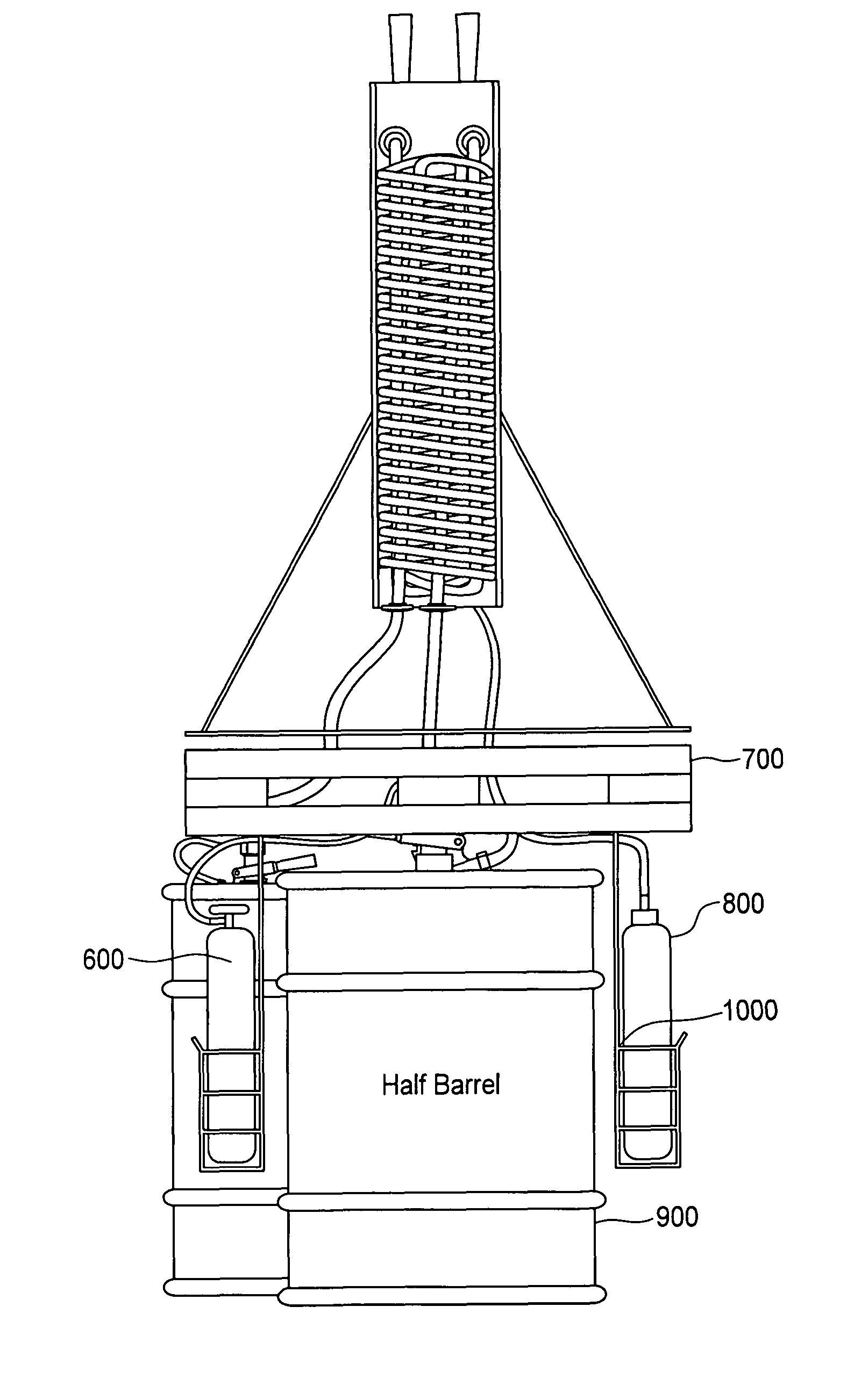
[0075]The figures and detailed descriptions of the figures do not reflect all embodiments of the present inventive device and system, but are provided for example and explanatory purposes, as described below. For example, certain embodiments of the present inventive device and system include one or more of balance legs, a structure protruding from the housing component and extending towards the keg couple that encloses at least one beer line, a combined single piece base plate and spacer plate, a carrying component, etc., and may involve various configurations of the set up as described herein, even if not specifically shown in the figures.

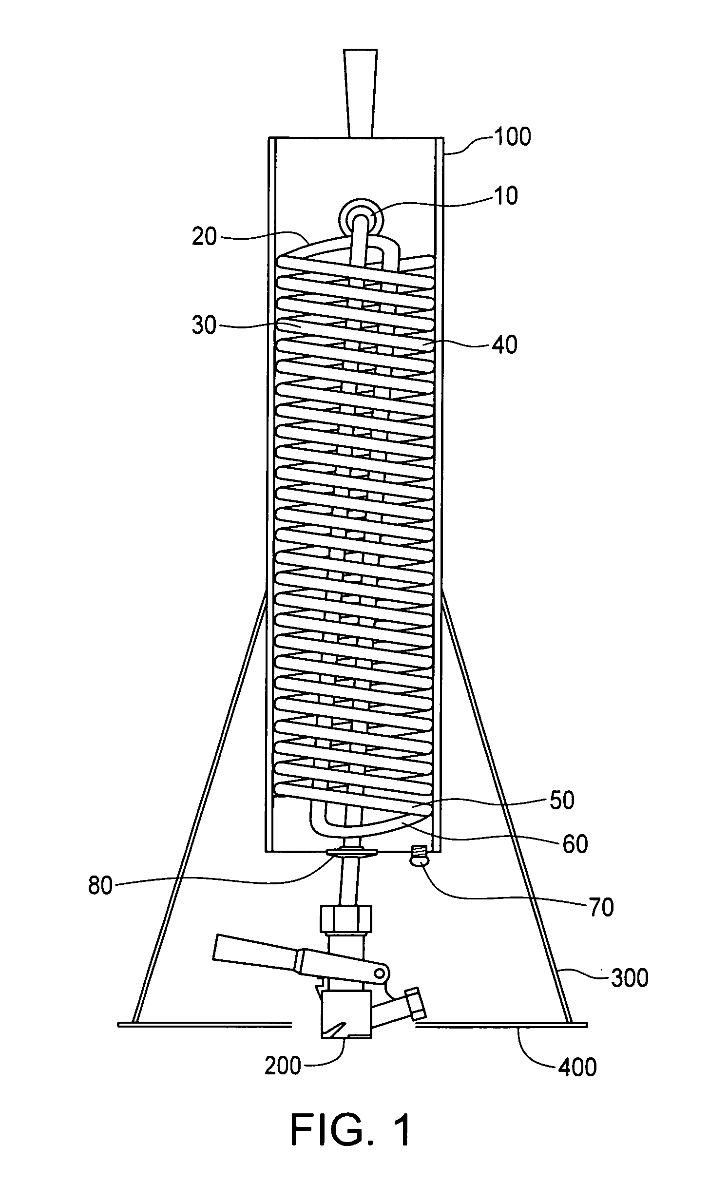
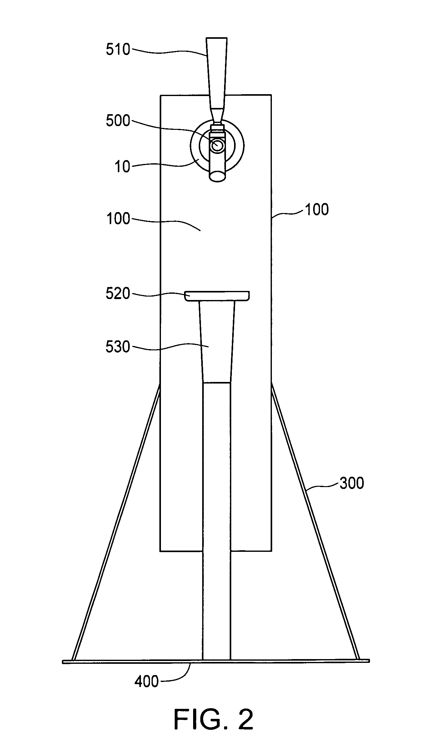
[0076]FIG. 1 shows a back internal view of single faucet embodiment of the present invention. Component (10) is the back of the beer shank and washer that is part of the faucet. The plastic beer line connects to this shank so beer can flow from the coils and out through the faucet. Component (20) refers to the wide portion of a plastic beer line u...


PUM


Abstract

The present invention provides an easy to use, convenient, compact, energy efficient, labor efficient, cost-effective, fast, safe, neat, electricity-independent, self-contained, portable beer dispensing device and system that uses CO2 or other acceptable gas to maintain the freshness of beer, presents a ready height and arrangement for dispensing chilled fresh beer, and can be used in a variety of professional, casual, indoor and / or outdoor settings. The present invention chills beer before it is dispensed but after it has been removed from the keg. The present invention incorporates use of a gas tank to propel beer from the keg, through the beer dispensing device and system so that the beer inside the keg will not go flat. The present invention offers a convenient arrangement of its components that simplifies its use, transport, set up, and break down. The present invention also provides a space efficient arrangement for dispensing chilled, draft beer.

Description

BACKGROUND OF THE INVENTION[0001]1. Field of the Invention[0002]The present invention generally relates to a device and system for dispensing beverages, such as beer. More particularly, the present invention provides an easy to use, convenient, compact, energy efficient, labor efficient, cost-effective, fast, safe, neat, electricity-independent, portable beer dispensing device and system that can be used to dispense fresh chilled beer.[0003]2. Description of Related Art[0004]Two types of beer dispensing device systems are conventionally used to dispense beer from a keg.[0005]The first beer dispensing device system type is a heavyweight, commercial system involving heavy pressure bottles of compressed carbon dioxide (CO2) gas operating through regulators and pressure lines for pressurizing one or more kegs. While such commercial systems advantageously use CO2 dispensing systems to prevent air from contacting the beer in the keg to keep the beer fresh for a longer period, such systems...

Claims


Application Information

Patent Timeline
Patent Type & Authority Patents(United States)
IPC IPC(8): B67D7/80B67D1/04B67D1/08
CPCB67D1/0406B67D1/0412B67D1/0857
Inventor WATTS, LARZ
Owner WATTS LARZ
Why Eureka
Try Eureka