Vibrating dental devices

a dental device and vibrating technology, applied in dental tools, dental surgery, medical science, etc., can solve the problems of cumbersome devices, difficult construction, high cost, etc., and achieve the effect of enhancing boney remodeling and speeding up boney remodeling

Inactive Publication Date: 2015-05-12
ADVANCED ORTHODONTICS & EDUCATION ASSOC LLC
View PDF98 Cites 26 Cited by
  • Summary
  • Abstract
  • Description
  • Claims
  • Application Information

AI Technical Summary

Benefits of technology

[0021]In a third embodiment, an improved connector is provided for connecting the bite plate to an extraoral vibrator, wherein the connector is asymmetric and thus prevents the user from inserting the plate upside down. The connector comprises a flare at the midline of the bite plate with depressions therein so that the matching protrusions on the vibrator fit thereinto. The depressions are offset from the central axis of the connector, thus the connector cannot be accidentally inserted upside down. The flare has a cylindrical shaft protruding therefrom for insertion into an appropriately shaped receptacle on the vibrator. The shaft has matching pins or protrusions on each side of the shaft, at the end near the bite plate, and there are corresponding depressions in the receptacle on the vibrator. This particular connector is a snap fit connector, configured so that only manual force is needed to insert and remove the bite plate. The snap fit in this instance is accomplished with a groove on the cylindrical shaft into which a circular spring in the vibrator will fit into. The application of a small amount of force stretches the spring slightly, allowing the device to be removed.
[0030]Generally speaking, the vibrator(s), and optional battery, on / off switch and circuitry are placed directly on the bite plate and hermetically sealed with no extraoral protrusions, thus allowing the most compact bite plate, preventing drooling and maximizing patient compliance. In preferred embodiments, the core may contain depressions therein for fitting various components thereinto, thus maintaining the generally planar surface of the bite plate and maintaining a thin cross section.
[0032]One or more vibrators can be placed on the plate, e.g., one on each side, or one for each of three tridents or four quadrants, as shown in FIG. 5. Where more than one vibrator is used, the vibrators should be synchronized when in use, so that the vibrations do not cancel each other out. In the alternative, the various portions of the bite plate can be separated with a thin divider portion of elastomeric material that serves to dampen the vibration and prevent its transfer to another portion of the bite plate. Either embodiment can be provided with control circuitry to either synchronize the motors, or to use the motors individually, thus vibrating only certain teeth.
[0033]The dental plate itself generally contains a stiff core, such as metal or rigid plastic onto which are placed the vibrator, and optional on / off switch, battery and the circuitry, as needed to run the device. Other stiff core materials can also be employed including ceramic, polymers and resins. However, aluminum and steel are preferred as easy to work with, inexpensive and having some flex, although certain plastic materials, such as polycarbonate, may be preferred as inexpensive and easily molded to fit components.
[0034]The dental plate can then be covered with a liquid-tight, elastic polymeric material to protect the user's teeth from the metal, to isolate any electrical components, and to provide a biocompatible and pleasant mouth feel. This is important for an intraoral embodiment, but the coating is optional on an extraoral device. Coatings, such as silicone rubber, polyethylene (PE), high density PE (HDPE), polycarbonate, polyurethane, polypropylene (PP), polyvinylchloride (PVC), polymethyl methacrylate, polyvinylidene fluoride, polyesters, acrylics, vinyl, nylon, rubber, latex, Teflon, or similar material, and combinations thereof may be used.
[0038]The devices can be used alone, or in combination with other orthodontic devices. In some embodiments, the appliance can be used to speed boney remodeling in orthodontic uses with traditional orthodontic fixed appliances or aligner based treatments or any other appliance used for tooth movement. In other embodiments the appliance can be used to enhance boney remodeling in periodontal and oral surgical uses.

Problems solved by technology

Although effective, this widely accepted approach takes about twenty four months on average to achieve success.
The devices are cumbersome, difficult to construct, expensive and are very difficult to use, thus reducing patient compliance.
Further, the dental plate is brass, and is very unpleasant to bite on, thus necessitating a second exterior coating and further complicating manufacture and cost.
However, there is no recognition in either patent that the vibratory device can be used for alveolar bone remodeling or more rapid tooth movement.
Furthermore, the shape of the dental plate in each case is a very flat U- or Y-shaped member that is largely ineffective for remodeling dentoalveolar bone.
Additionally, the vibration is not optimized in frequency and amplitude for remodeling.
Finally, neither device is entirely intraoral, and the extraoral component may cause drooling and inhibit patient compliance.
The extraoral component may also lead to inhibition about use of the device in certain settings.
All of these shortcomings reduce the effectiveness of these devices for craniofacial remodeling uses.
U.S. Pat. No. 6,632,088 describes a bracket with powered actuator mounted thereto to provide vibration, but this device is cumbersome, and thus may affect patient comfort and ultimately patient acceptance of the device.
Further, the device locks to the bracket and archwire, and vibration of the tooth through the bracket is less than optimal, causing wear to the tooth enamel and causing discomfort.
WO2007116654 describes another intraoral vibrating mouthpiece, but the mouthpiece is complex, designed to fit over the teeth and will be expensive to manufacture.
Further, to the extent that this device vibrates the brackets, it suffers from the same disadvantages above.

Method used


Image

  • Vibrating dental devices
  • Vibrating dental devices
  • Vibrating dental devices

Examples


example 1

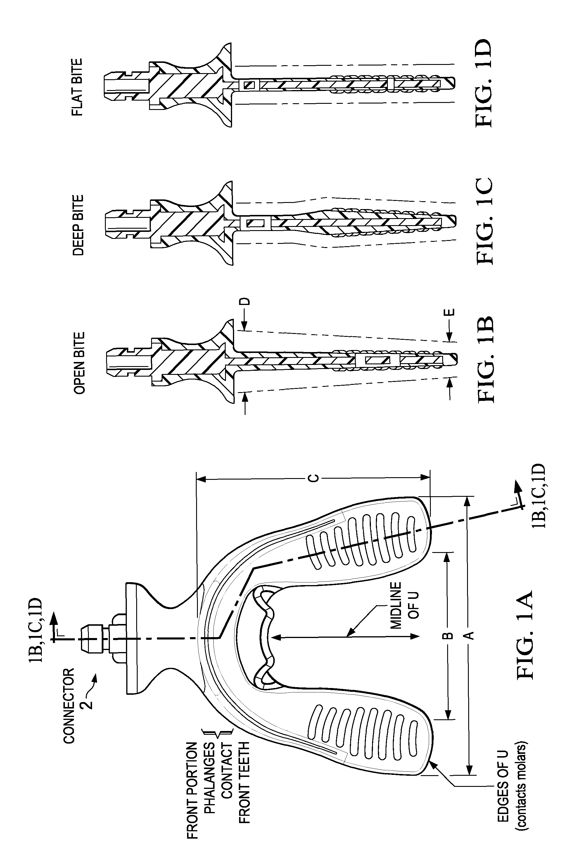
[0048]The improved mouthpieces or bite plates are available in two sizes (small and large) based primarily on the anatomical dimensions of the patient's dental arches. Each size is available in three profiles based primarily on the type of malocclusion (open bite, deep bite and normal flat plane occlusion).

[0049]In the bite plates shown in FIG. 1, the phalanges that contact the lingual and buccal (inside and front) surface of the teeth are omitted for clarity, but such phalanges or edges are preferred since these edges allow greater contact with the teeth for improved comfort and improved transmission of the cyclic forces. Also shown in FIGS. 1B-D are optional ridges on the surface of the bite plate.

[0050]The sizes and profiles have been developed based on a statistical analysis of a sample population and are intended to allow for a maximum contact of teeth with the bite plate in a high percentage of patients and case types. The dimensions given in Table 1 are based on a minimum thi...

example 2

[0059]In a second embodiment, an improved extraoral vibrator has a more stable vibrator with improved performance characteristics of decreased sound and low variability frequency and force. In particular, the improved vibrator has a noise level less than 55 dB when measured at 6 inches, and preferably less than 50, 45, 40, or 35 dB. The improved vibrator provides a frequency at 20-40 Hz, preferably 30 Hz with a variance of only 2 Hz, and preferably 1 or 0.75 Hz. This is particularly important where the patient may move around during use, whereby lower quality vibrators may vary substantially with motion and / or orientation and thus provides an inconsistency that may be less efficacious, and may make FDA clearance of such a device more difficult. Further, the improved vibrator provides force at 0.1-0.5 Newtons, and preferably at 0.20 Newtons (20 grams) with a variance of ±0.05 N, and preferably less than ±0.03 N.

[0060]Consistency of frequency and force is achieved herein via a feedbac...

example 3

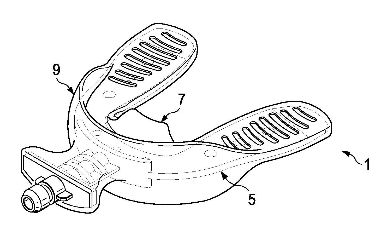
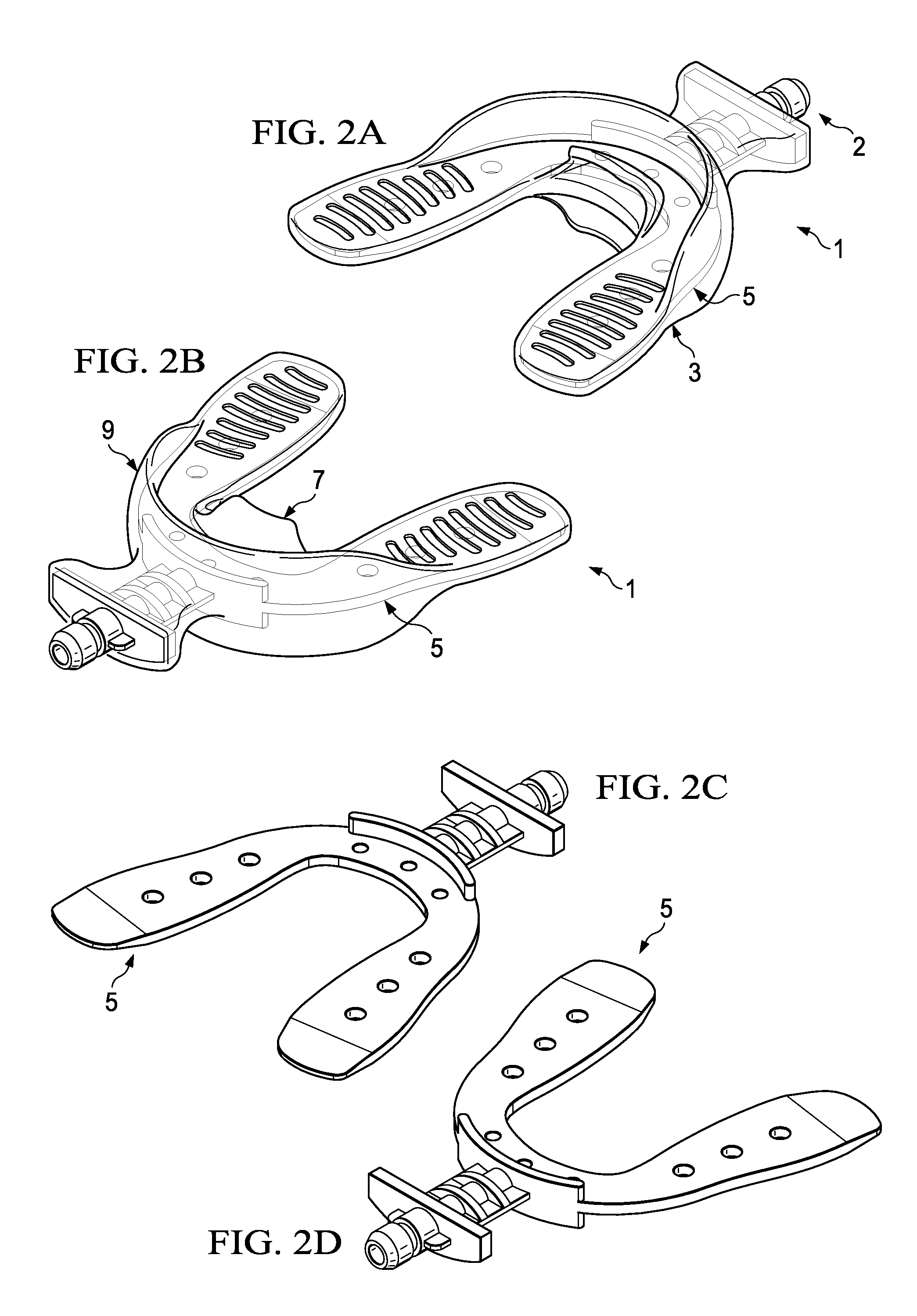
[0063]The bite plate of FIGS. 2A-D show the substantially U shaped bite plate 1 with clear overcoat 3 covering a stiff inner core 5 (shown as solid). Also shown is the lingual phalange or edge 7 for contacting the lingual surfaces of the teeth, in this instance only the front or anterior teeth (see labial area of FIG. 6A), and facial phalange 9 for contacting the facial surfaces of the teeth, as well as connector 2. The phalanges provide additional force transferring contacts with the teeth, but also aid in maintaining the correct position of the bite plate during use. Without the phalanges, the bite plate will vibrate away from the optimal position during use.

[0064]FIGS. 3A-D shows the details of the bite plate of FIGS. 2A-D, and FIGS. 4A-B includes sizing details of a preferred embodiment of the connector. In a basic configuration the connector 21 is a snap fit connector having a cylindrical shaft 23 that fits into a socket or receptacle on the vibrator. The shaft is of diameter 6...


PUM


Abstract

A variety of improvements to the vibrating devices for dental remodeling are provided, including improved bite plate designs that accommodate common patient bite structure, a connector for a bite plate, a sizing tray for same, as well as better motors providing improved performance characteristics for an extraoral vibrator, and a completely intraoral vibrating dental plate with very thin cross section.

Description

PRIOR RELATED APPLICATIONS[0001]This application is a Continuation-in-Part of US2008227046 (Ser. No. 11 / 773,849), filed Jul. 5, 2007, which claims priority to 60 / 906,807, filed Mar. 14, 2007.FEDERALLY SPONSORED RESEARCH STATEMENT[0002]Not applicable.REFERENCE TO MICROFICHE APPENDIX[0003]Not applicable.FIELD OF THE INVENTION[0004]The invention relates to vibrating dental devices for correcting malocclusion.BACKGROUND OF THE INVENTION[0005]Orthodontics is a dental specialty that treats malocclusion through the movement of teeth as well as control and modification of facial growth. This process is usually accomplished by using a continuous mechanical force to induce bone remodeling, thereby enabling the teeth to move to a better position. In this approach, orthodontic appliances provide a continuous static force to the teeth via an archwire connected to brackets affixed to each tooth or via a removable appliance such as an aligner, or some similar accessory, that fits over the dentitio...

Claims


Application Information

Patent Timeline
Patent Type & Authority Patents(United States)
IPC IPC(8): A61C3/00A61C7/00A61C7/08
CPCA61C7/00A61C7/008A61C7/08A61C7/002A61C1/0015A61C7/12A61C2204/005
Inventor SPAULDING, GLENNLING, JEREMYKAUFMAN, MICHAEL E.LOWE, MICHAEL K.
Owner ADVANCED ORTHODONTICS & EDUCATION ASSOC LLC
Why Eureka
Try Eureka