System to use digital cameras and other sensors in navigation

a technology of digital cameras and sensors, applied in traffic control systems, navigation instruments, instruments, etc., can solve the problems of cost, computational complexity of slam and visnav, and incomplete work on estimating the covariance of projective transformation

Inactive Publication Date: 2015-05-12
THE UNITED STATES OF AMERICA AS REPRESENTED BY THE SECRETARY OF THE NAVY
View PDF2 Cites 90 Cited by
  • Summary
  • Abstract
  • Description
  • Claims
  • Application Information

AI Technical Summary

Problems solved by technology

However, prior work on estimating the covariance of the projective transformation is incomplete.
When the same landmarks appear in multiple photographs, the measurements that are made from those photographs will have correlated error characteristics.
These advantages come with a cost—SLAM is more computationally complex than VISNAV.
Another consideration for SLAM is that, although the relative location of landmarks can be determined very accurately, the absolute location of landmarks is subject to the absolute error that exists in the navigation system's pose estimate.
That is, the SLAM solution for the location of all the landmarks might include some constant error with respect to their true location, which will be a function of the error in the navigation system.
Then the error sources are used to derive an estimate for Rε and Ψ. A Monte Carlo analysis of the covariance estimation algorithm is performed, which reveals that failure modes may occur that produce non-Gaussian attitude and position errors.
Misalignment in between the axes of the camera and the axes of the INS, errors in the camera calibration parameters, errors in the position coordinates of the ith landmark and errors in registering its pixel location on the imaging plane (i.e., errors in ui and vi) will all contribute to errors in the final position and attitude.
That leaves the landmark survey error and the pixel registration error, which will be described here.
Numerical errors in computing the the Ĉnb matrix may have caused it to become non-orthogonal.
Failure to compensate for this can cause the filter to diverge.
Although the algorithm presented above appears sound, if it is put into practice without adjustments it will produce poor estimates for the camera's position and attitude.
This makes the B and ΔB matrices ill-conditioned.
It is important to note that normalizing is not an optional procedure—failure to normalize the pixel and landmark coordinates will lead to poor results.
When using normalized coordinates for pixels and landmarks, the noise levels for pixel registration and landmark surveying also change due to the normalization.
This results in a three step process to relate Pη to Euler angle errors.
When flipping occurs, the camera solution will have a large, non-Gaussian attitude and position error.
Fortunately, because the errors that result from this are so large, it is easy to detect when this has occurred and to keep it from being included in the navigation solution.
Specifically, in the absence of a large acceleration signal, yaw (and yaw gyro bias) is unobservable or weakly observable in an integrated INS / GPS system.
It is apparent from looking at the filter yaw error in FIG. 23 that the INS / GPS configuration suffers from poor observability of the yaw gyroscope bias, as evidenced by the poor estimation of yaw for t<180 seconds.
This lack of observability stems from the fact that the acceleration signals are not strong enough to make these two states observable.
Un-modeled errors include timing synchronization errors between sensors, feature point mismatches, camera calibration errors, and camera installation misalignment errors.

Method used


Image

  • System to use digital cameras and other sensors in navigation
  • System to use digital cameras and other sensors in navigation
  • System to use digital cameras and other sensors in navigation

Examples


Embodiment Construction

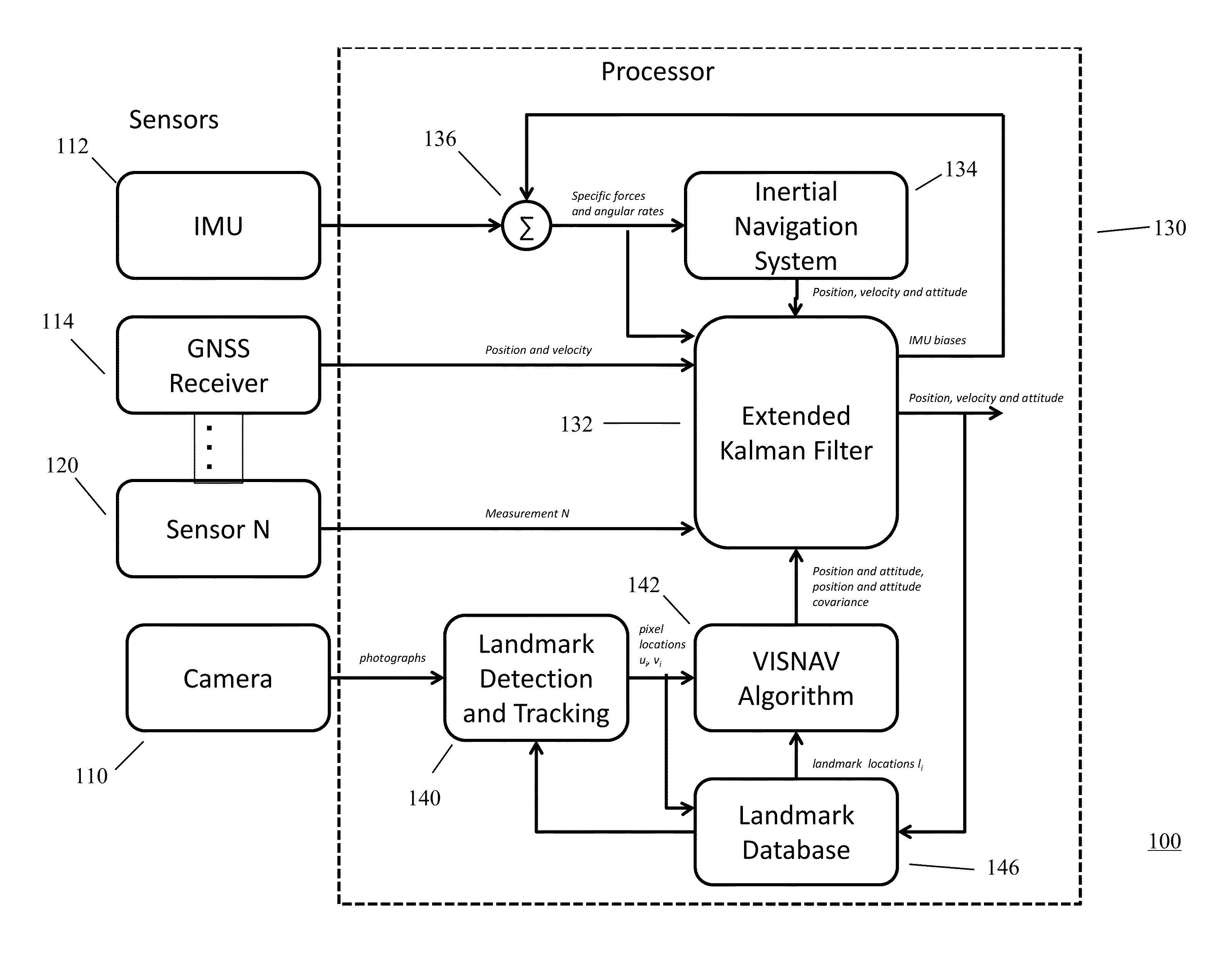
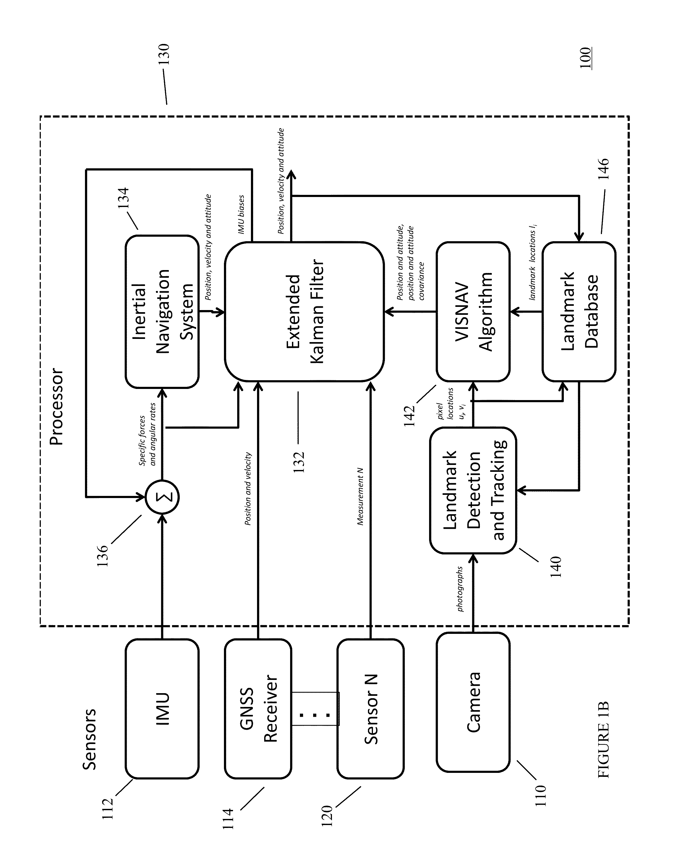
[0036]One preferred embodiment of the navigation system of the present invention includes a GPS receiver, an Inertial Measurement Unit, a Magnetometer triad, a digital camera, and a microprocessor. Data is collected and the algorithms that make up the invention were applied in post-processing. In one embodiment, a van was driven through Liberty Station in San Diego, Calif. for an hour. Data from all of the sensors was recorded and used in post-processing to validate the sensor fusion algorithms that have been developed.

[0037]This invention can be used in all military or non-military applications when navigation needs to occur in a GPS-denied environment, such as indoors, underground, or underneath dense foliage. It can also be used as a backup to GPS to provide robust navigation in the event that GPS becomes unavailable.

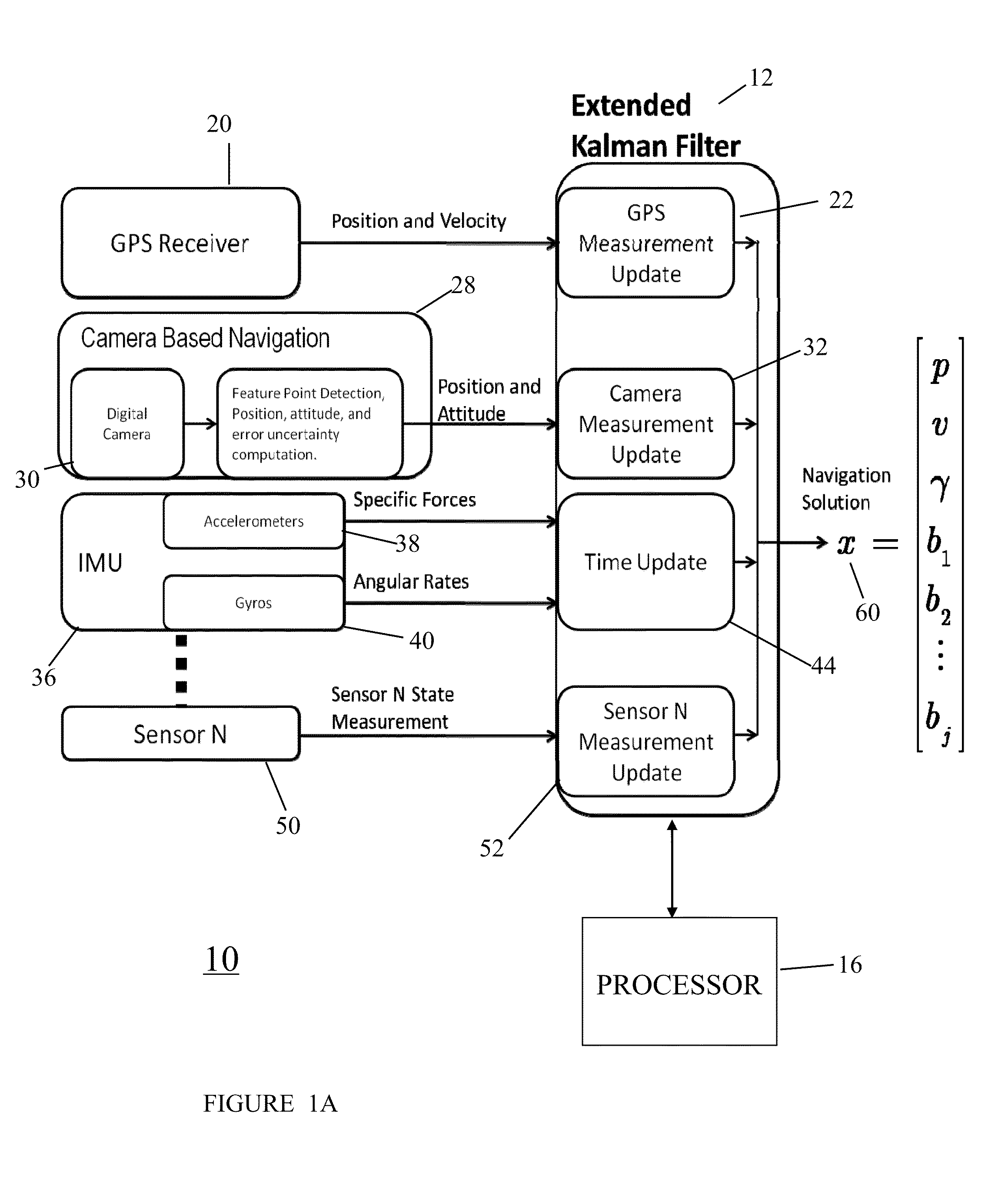
[0038]The invention estimates a navigation solution based on inputs from different sensors, including at least a digital camera. Other sensors that may be included a...


PUM


Abstract

In one preferred embodiment, the present invention provide a navigation system for a movable platform comprising a GNSS receiver sensor for providing position signals representative of the estimated current position of the movable platform; a camera sensor for providing photographic images representative of the surroundings of the movable platform; and an IMU (Inertial Measurement Unit) sensor for providing specific force and angular rate signals representative of the current specific forces and rate of the movable platform. A processor is responsive to the camera photographic images to estimate the position and attitude of the movable platform, the covariance of the position and attitude estimates and the covariance of consecutive position and attitude estimates. The processor is responsive to the GNSS receiver's estimated position signal, the camera's estimated position and attitude signal, the camera's estimated position and attitude covariance, the camera's estimated correlation of the covariance of consecutive position and attitude estimates, and the specific force and angular rate signals, for providing a navigation solution representative of the estimated current position, velocity, and attitude of the movable platform.

Description

CROSS-REFERENCE TO RELATED PATENT APPLICATIONS[0001]The present application is related to provisional patent application Ser. No. 61 / 589,410, filed Jan. 23, 2012, entitled SYSTEM TO USE DIGITAL CAMERAS AND OTHER SENSORS IN NAVIGATION, assigned to the same assignee as the present invention, the details of which are hereby incorporated by reference herein, and priority is claimed herein under 35 USC §119(e).FEDERALLY-SPONSORED RESEARCH AND DEVELOPMENT[0002]This invention is assigned to the United States Government and is available for licensing for commercial purposes. Licensing and technical inquiries may be directed to the Office of Research and Technical Applications, Space and Naval Warfare Systems Center, Pacific, Code 72120, San Diego, Calif., 92152; voice (619)553-2778; email T2@spawar.navy.mil.BACKGROUND OF THE INVENTION[0003]In the prior art, landmarks that were triangulated using a navigation system and a camera used computationally expensive algorithms such as particle filt...

Claims


Application Information

Patent Timeline
Patent Type & Authority Patents(United States)
IPC IPC(8): G01C21/16G01C21/00
CPCG01C21/00G01S5/16G06T7/73G06T7/77G06T7/246G06T7/277G01S19/485G01C21/1654G01C21/1656
Inventor LEMAY, LEE C.GORGEN, JUSTIN E.GEBRE-EGZHIABHER, DEMOZ
Owner THE UNITED STATES OF AMERICA AS REPRESENTED BY THE SECRETARY OF THE NAVY
Why Eureka
Try Eureka