
Secure active element machine

a technology of active elements and active elements, applied in the field of computing, can solve the problems of difficult apprehending of adversaries, hijacking with malware, and difficult use of aem computations, and achieve the effect of enhancing the capability of a computational procedur

Active Publication Date: 2015-05-12
AEMEA
View PDF7 Cites 3 Cited by
  • Summary
  • Abstract
  • Description
  • Claims
  • Application Information

AI Technical Summary

Benefits of technology

The patent describes a new method for writing computer programs that are resistant to hacking and malicious attacks. The method uses a fixed representation of the way the program instructions are executed, which makes it easier for malicious code to exploit vulnerabilities in these programs. However, this fixed representation makes it harder for malicious attacks to sabotage the program's purpose. The method is designed to be used in applications where reliability, security, and performance are of high importance, such as protecting critical infrastructure and financial transactions. The method utilizes a new approach called AEM (Advanced Executable Model) that runs on specific hardware designed for AEM computation, resulting in significantly faster performance.

Problems solved by technology

AEM programs are designed so that the purpose of the AEM computations are difficult to apprehend by an adversary and hijack with malware.

Method used


Image

  • Secure active element machine
  • Secure active element machine
  • Secure active element machine

Examples


case 1

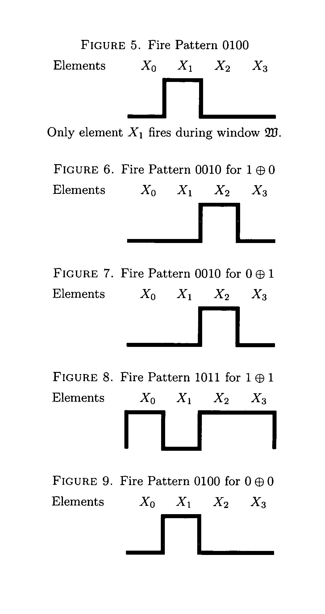
[0322] Element A fires at time t=0 and element B doesn't fire at t=0.

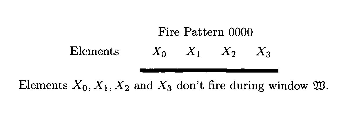
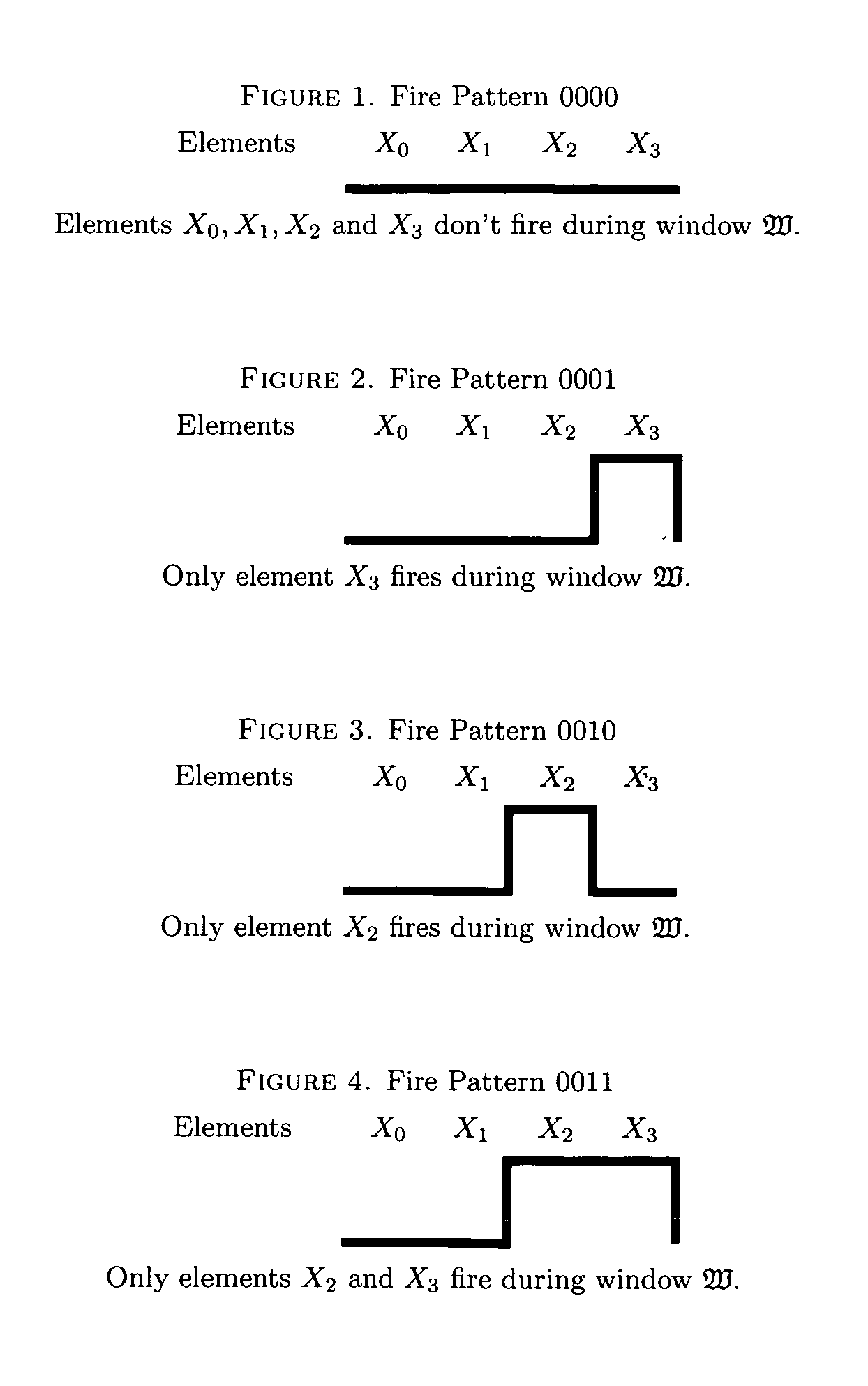
[0323]Element X0 receives a pulse from A with amplitude 2 at time t=2. Element X0 doesn't fire because its threshold=3. Element X1 receives a pulse from A with amplitude −2 at time t=2. Element X1 doesn't fire during W because X1 has threshold=−1. Element X2 receives a pulse from A with amplitude 2. Element X2 fires at time t=2 because its threshold is 1. Element X3 receives a pulse from A with amplitude 2 but doesn't fire during window W because X3 has threshold=3.

case 2

[0324] Element X0 receives a pulse from B with amplitude 2 at time t=2.

[0325]Element X0 doesn't fire because its threshold=3. Element X1 receives a pulse from B with amplitude −2 at time t=2. Element X1 doesn't fire during W because X1 has threshold=−1. Element X2 receives a pulse from B with amplitude 2. Element X2 fires at time t=2 because its threshold is 1. Element X3 receives a pulse from B with amplitude 2, but doesn't fire during window W because X3 has threshold=3.

case 3

[0326] Element A fires at time t=0 and element B fires at t=0.

[0327]Element X0 receives two pulses from A and B each with amplitude 2 at time t=2. Element X0 fires because its threshold=3. Element X1 receives two pulses from A and B each with amplitude −2 at time t=2. Element X1 doesn't fire during W because X1 has threshold=−1. Element X2 receives two pulses from A and B each with amplitude 2. Element X2 fires at time t=2 because its threshold is 1. Element X3 receives two pulses from A and B each with amplitude 2. Element X3 fires at time t=2 because X3 has threshold=3.


PUM


Abstract

Based upon the principle of Turing incomputability, and novel properties of the Active Element Machine, a malware-resistant computing machine is constructed. This new computing machine is a non-Turing, non-register machine (non von-Neumann), called an Active Element Machine (AEM). AEM programs are designed so that the purpose of the computation is difficult to apprehend by an adversary and hijack with malware. These methods can help hinder reverse engineering of proprietary algorithms and hardware design.Using quantum randomness, the AEM can deterministically execute a universal digital computer program with active element firing patterns that are Turing incomputable. In some embodiments, a more powerful computational procedure is demonstrated than Turing's computational procedure (digital computer procedure). Current digital computer algorithms can be derived or designed with a Turing machine computational procedure. A novel class of computing machines is built where the purpose of the program's execution is difficult to apprehend (Turing incomputable).

Description

RELATED APPLICATIONS[0001]This application claims priority benefit of U.S. Provisional Patent Application Ser. No. 61 / 462,260, entitled “Navajo Active Element Machine” filed Jan. 31, 2011, which is incorporated herein by reference. This application claims priority benefit of U.S. Provisional Patent Application Ser. No. 61 / 465,084, entitled “Unhackable Active Element Machine” filed Mar. 14, 2011, which is incorporated herein by reference. This application claims priority benefit of U.S. Provisional Patent Application Ser. No. 61 / 571,822, entitled “Unhackable Active Element Machine Using Randomness” filed Jul. 6, 2011, which is incorporated herein by reference. This application claims priority benefit of U.S. Provisional Patent Application Ser. No. 61 / 572,607, entitled “Unhackable Active Element Machine Unpredictable Firing Interpretations” filed Jul. 18, 2011, which is incorporated herein by reference. This application claims priority benefit of U.S. Provisional Patent Application Se...

Claims


Application Information

Patent Timeline
Patent Type & Authority Patents(United States)
IPC IPC(8): G06F21/00G06F21/75
CPCG06F21/75G06F9/448
Inventor FISKE, MICHAEL STEPHEN
Owner AEMEA
Learn More