
Barrel cam rotating cylinder engine

a rotating cylinder and barrel cam technology, applied in the direction of liquid fuel engines, machines/engines, mechanical equipment, etc., can solve the problems of engine efficiency reduction and engine with high frontal area

Active Publication Date: 2015-05-19
MCNITT MARK
View PDF16 Cites 3 Cited by
  • Summary
  • Abstract
  • Description
  • Claims
  • Application Information

AI Technical Summary

Benefits of technology

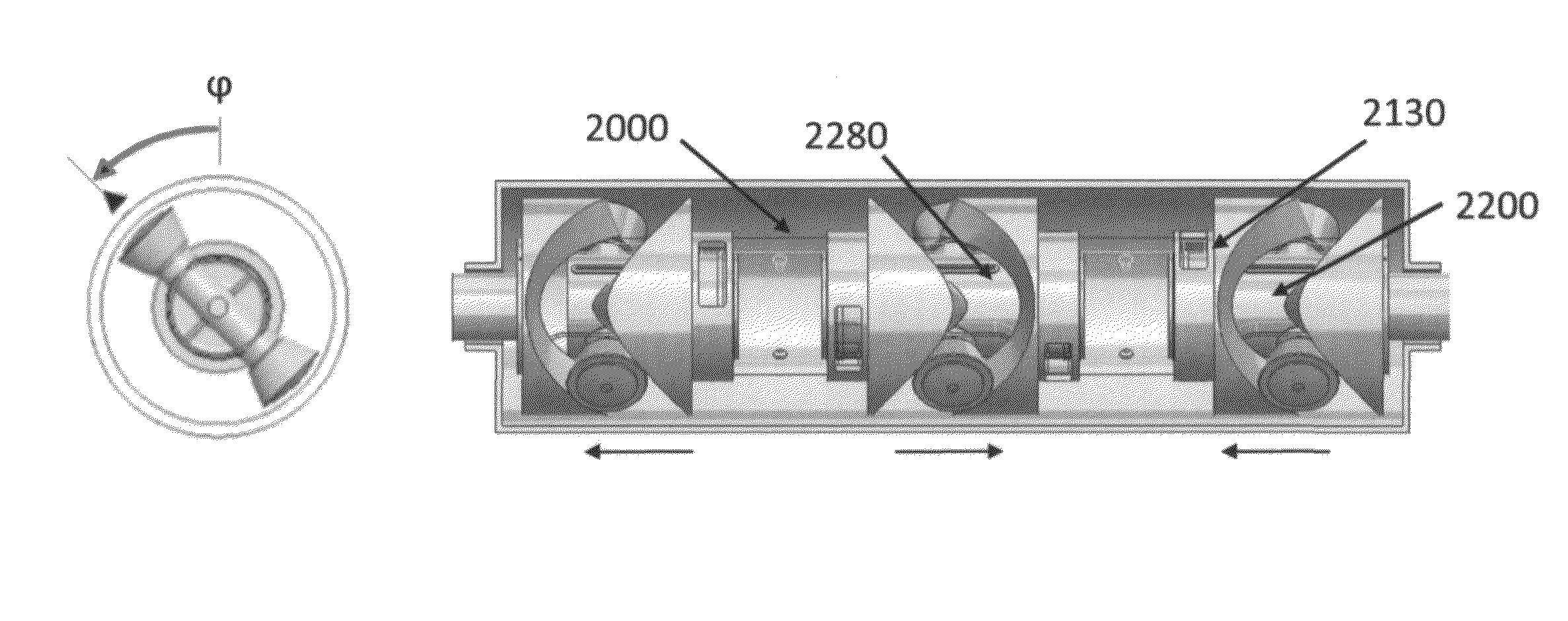
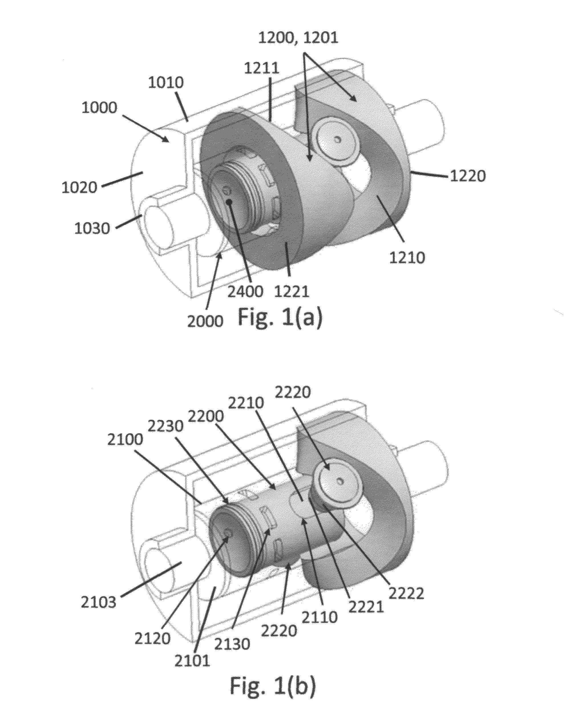
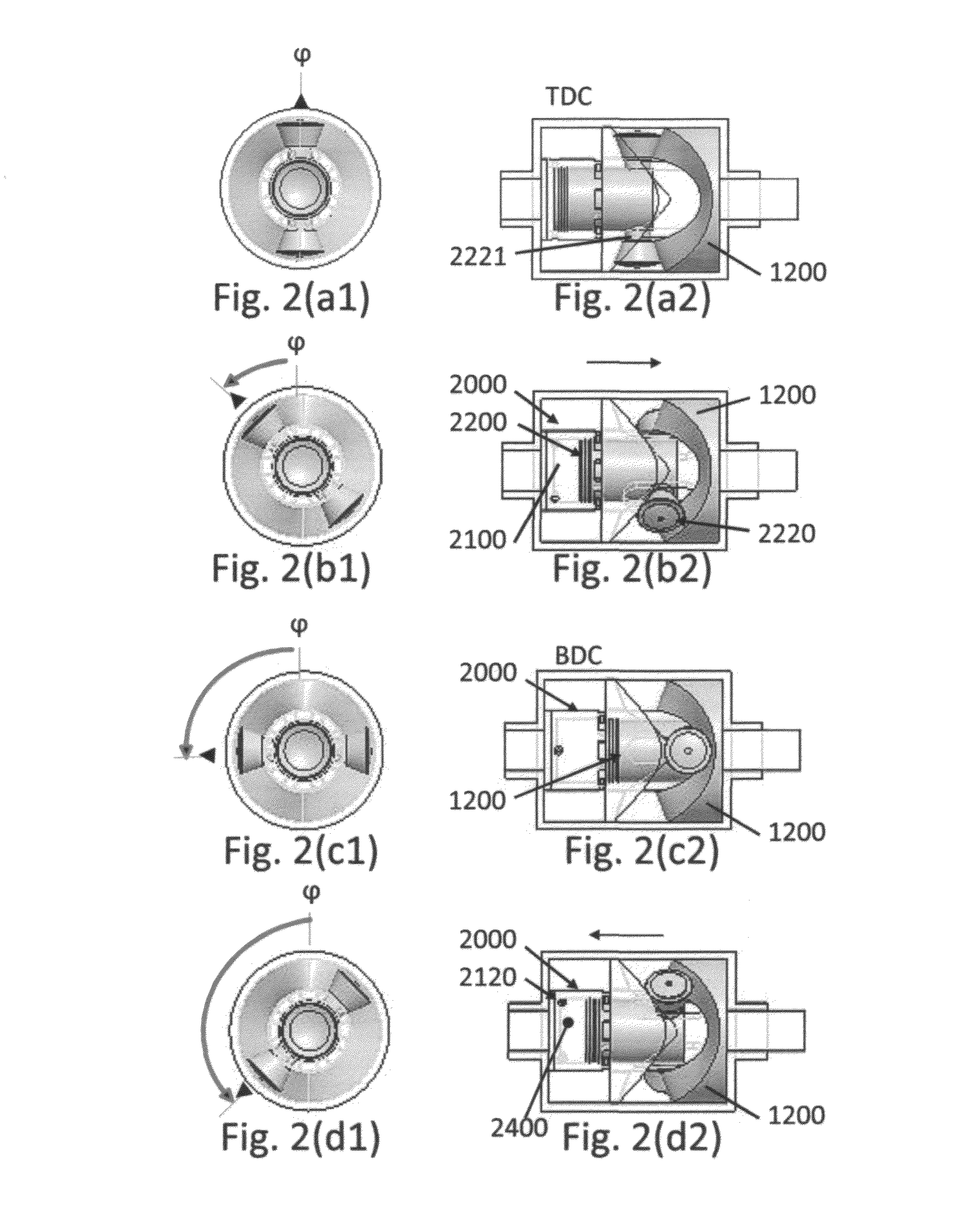
The invention is an internal combustion engine with a rotating cylinder and cam components. The engine has one or more pistons that move back and forth in the cylinder. The cam components are connected to the engine case and are positioned around the rotating cylinder. The cam components have cam rollers that are connected to the pistons through cam path apertures in the cylinder. The engine can have different numbers of pistons and can use fuel injection through the pistons. The engine also has manifold ports and fuel injection ports. The invention allows for improved engine performance and fuel efficiency.

Problems solved by technology

All these moving parts result in friction losses that decrease the efficiency of the engine.
The high component count also results in engines with high frontal areas.

Method used


Image

  • Barrel cam rotating cylinder engine
  • Barrel cam rotating cylinder engine
  • Barrel cam rotating cylinder engine

Examples


Embodiment Construction

[0056]Improved engine designs that include reduced numbers of parts, lower friction losses, reduced vibration, and smaller frontal area would greatly benefit automotive and aircraft applications. Frontal area reductions would be especially beneficial for aircraft applications, due to the reduced drag contribution of the engines and their cowlings. Traditional piston engine designs, with piston rods, crankshafts, and cam driven valves are inherently burdened by high part counts, sizable friction losses, and large frontal areas. Even advancements in rotary engines and opposed piston configurations continue to be limited in the efficiencies they can produce in many of these attribute areas.

[0057]A new engine configuration should be lighter in weight and preferably have a reduced frontal area profile for improved installation suitability. For automotive applications, a reduced frontal area profile would permit the engine to fit compactly in narrow spaces. For light aircraft applications...


PUM


Abstract

The present disclosure is directed toward implementations of internal combustion engines. The disclosure describes various embodiments of internal combustion engines where most of the internal elements rotate. Such engines allow for more efficient transfer of the energy created by combustion to the motive components of a vehicle such as wheels or propellers. One specific embodiment includes a rotating cylinder with a single piston which both reciprocates and rotates. The rotating motion of the piston is transferred to the cylinder, which in turn is connected to a driveshaft. Various embodiments of the invention employ differing numbers and configurations of pistons. All embodiments have the advantage of decreasing engine volume and increasing efficiency over traditional internal combustion engines.

Description

PRIORITY CLAIM[0001]This application discloses and claims subject matter that is disclosed in applicant's U.S. provisional application Ser. No. 61 / 478,026 that was filed Apr. 21, 2011.BACKGROUND OF THE INVENTION[0002]Traditional two and four stroke internal combustion engines are employed in many different applications. One primary application is to provide power for the motive force in cars, boats, airplanes and other vehicles. These types of engines generally employ a relatively high number of moving components, including camshafts, crankshafts, connecting rods, crankpins, and more, to transfer the motion from one or more reciprocating pistons into rotational movement. All these moving parts result in friction losses that decrease the efficiency of the engine. The high component count also results in engines with high frontal areas.[0003]Developing a two stroke engine with fewer components reduces the amount of energy lost to friction where each engine part contacts a separate eng...

Claims


Application Information

Patent Timeline
Patent Type & Authority Patents(United States)
IPC IPC(8): F01B13/04F02B57/00F02B75/36F02B75/24F02B75/18F02B75/22F01B3/00F02B25/08
CPCF01B3/00F02B2720/257F02B25/08F02B2730/018F02B2730/02F01B3/0002F01B3/0005F01B3/04F01B3/045F01B7/02
Inventor MCNITT, MARK
Owner MCNITT MARK
Learn More