Lattice tower assembly for a wind turbine

a technology of wind turbines and roofs, which is applied in the direction of wind energy generation, mechanical equipment, machines/engines, etc., can solve the problems of difficulty in transporting the tubular tower sections to the site, high cost disadvantage, and inability to meet the requirements of a dedicated road

Inactive Publication Date: 2015-05-26
GENERAL ELECTRIC CO
View PDF32 Cites 11 Cited by
  • Summary
  • Abstract
  • Description
  • Claims
  • Application Information

AI Technical Summary

Benefits of technology

[0010]In accordance with aspects of the invention, a lattice tower assembly for a wind turbine is disclosed. The lattice tower assembly includes a plurality of structural members connected together to define an open lattice tower. The structural members include a plurality of supports, a plurality of inner cross-support members, and a plurality of outer cross-support members. The inner and outer cross-support members are connect

Problems solved by technology

However, tubular poles use more steel than the lattice structure, resulting in a cost disadvantage with rising prices of steel.
For example, transporting the tubular tower sections to the site can be challenging because the sections can be twenty plus meters long and over four meters in diameter.
As such, in some instances, a dedicated road is needed, but may not be possible.
The cladding material 56, however, must be

Method used


Image

  • Lattice tower assembly for a wind turbine
  • Lattice tower assembly for a wind turbine
  • Lattice tower assembly for a wind turbine

Examples


Embodiment Construction

[0034]Reference now will be made in detail to embodiments of the invention, one or more examples of which are illustrated in the drawings. Each example is provided by way of explanation of the invention, not limitation of the invention. In fact, it will be apparent to those skilled in the art that various modifications and variations can be made in the present invention without departing from the scope or spirit of the invention. For instance, features illustrated or described as part of one embodiment can be used with another embodiment to yield a still further embodiment. Thus, it is intended that the present invention covers such modifications and variations as come within the scope of the appended claims and their equivalents.

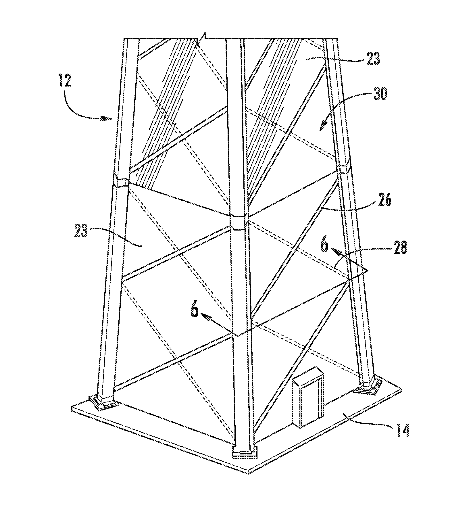
[0035]Generally, the present subject matter is directed to a lattice tower covering for a lattice tower structure of a wind turbine and a lattice tower assembly including the same. The lattice tower assembly typically includes a plurality of structural memb...


PUM


Abstract

The present subject matter is directed to a lattice tower covering and/or assembly for a wind turbine. The lattice tower assembly includes a plurality of structural members connected together to define an open lattice tower. The structural members include a plurality of supports, a plurality of inner cross-support members, and a plurality of outer cross-support members. The inner and outer cross-support members are connected between the supports so as to define one or more openings. The lattice tower covering includes one or more panel elements. Each of the panel elements are retained in position between the supports and cover at least a portion of one or more of the openings. Further, the lattice tower covering has a surface area defined by the plurality of supports and the one or more panel elements.

Description

FIELD OF THE INVENTION[0001]The present invention relates generally to wind turbines, and more particularly to an improved lattice tower covering for a wind turbine.BACKGROUND OF THE INVENTION[0002]Conventional wind turbine towers typically include a tubular pole or a lattice structure to support a wind turbine at a considerable height to capture wind energy. The tubular pole configuration is relatively more simple and easier to assemble than the lattice structure. However, tubular poles use more steel than the lattice structure, resulting in a cost disadvantage with rising prices of steel.[0003]Thus, lattice tower structures can have potential as an alternative to the tubular poles, especially for high hub applications and for wind turbines located in wind farms having challenging logistic requirements. For example, transporting the tubular tower sections to the site can be challenging because the sections can be twenty plus meters long and over four meters in diameter. As such, in...

Claims


Application Information

Patent Timeline
IPC IPC(8): F03D11/04E04H12/10
CPCF03D11/04F05B2240/9121E04H12/10E04B1/19F03D13/20Y02E10/72Y02E10/728E04B2001/199
Inventor FANG, BIAOPHELPS, ROBERT ALLANOLIPHANT, DAVID DRUEWEBER, WILLIAM CLARK
Owner GENERAL ELECTRIC CO
Why Eureka
Try Eureka