Electric power supply system and electric power supply method

a technology of electric power supply and electric power supply method, which is applied in the direction of engine-driven generators, battery/fuel cell control arrangements, transportation and packaging, etc., can solve the problem of the amount of electric power that can be supplied, and achieve the effect of efficient use of electric power

Inactive Publication Date: 2015-05-26
TOYOTA JIDOSHA KK
View PDF22 Cites 10 Cited by
  • Summary
  • Abstract
  • Description
  • Claims
  • Application Information

AI Technical Summary

Benefits of technology

[0012]According to this aspect, the secondary battery provided in the vehicle is connected to the building by the connecting device. As a result, electric power is able to be supplied from the electric power to the building.
[0015]In the aspect described above, the control apparatus may control the supply of electric power such that all of the electric power in the secondary battery is supplied to the building when the type of the vehicle is identified as a hybrid vehicle. That is, when the vehicle is a hybrid vehicle, the vehicle is able to run on fuel and is thus able to run even if all of the electric power is supplied to the building. As a result, electric power for the building can be ensured by supplying all of the electric power in the secondary battery to the building.
[0016]In the aspect described above, the control apparatus may control the supply of electric power such that a portion of all of the electric power charged to the secondary battery is supplied to the building when the type of the vehicle is identified as a hybrid vehicle and the amount of fuel remaining in the vehicle is less than a predetermined amount. That is, if all of the electric power in the secondary battery is supplied to the building, the vehicle may not be able to run. Therefore, by supplying only a portion of the electric power in the secondary battery to the building and leaving the rest, it is possible to both supply electric power to the building and run the vehicle.
[0017]In the structure described above, the control apparatus may i) obtain information indicative of the type of the vehicle, the amount of fuel remaining in the vehicle, and a charging amount of the secondary battery, ii) determine the amount of electric power to supply based on the obtained information, and iii) control the supply of electric power such that the determined amount of electric power to supply is supplied to the building. As a result, it is possible to both supply electric power to the building and run the vehicle.
[0021]Also, in the structure described above, the control apparatus may control the supply of electric power such that refresh discharging electric power of the secondary battery is supplied as a first priority. That is, refresh discharging is performed to prevent the secondary battery from degrading, and the electric power that is discharged during refresh discharging ends up being wasted. Preferentially supplying this refresh discharging electric power to the building, however, enables electric power to be used efficiently.
[0023]Moreover, in the structure described above, after the vehicle has finished being used each day, the control apparatus may control the supply of electric power such that electric power remaining in the secondary battery is supplied to the building during daytime electric utility hours or intermediate electric utility hours. That is, the electricity charges for the building can be reduced by supplying that electric power to the building during daytime electric utility hours or intermediate electric utility hours (on a plan with three different rates depending on the time of day).

Problems solved by technology

However, the amount of electric power that is able to be supplied from the vehicle to the house is different with an electric vehicle than it is with a hybrid vehicle.

Method used


Image

  • Electric power supply system and electric power supply method
  • Electric power supply system and electric power supply method
  • Electric power supply system and electric power supply method

Examples


Embodiment Construction

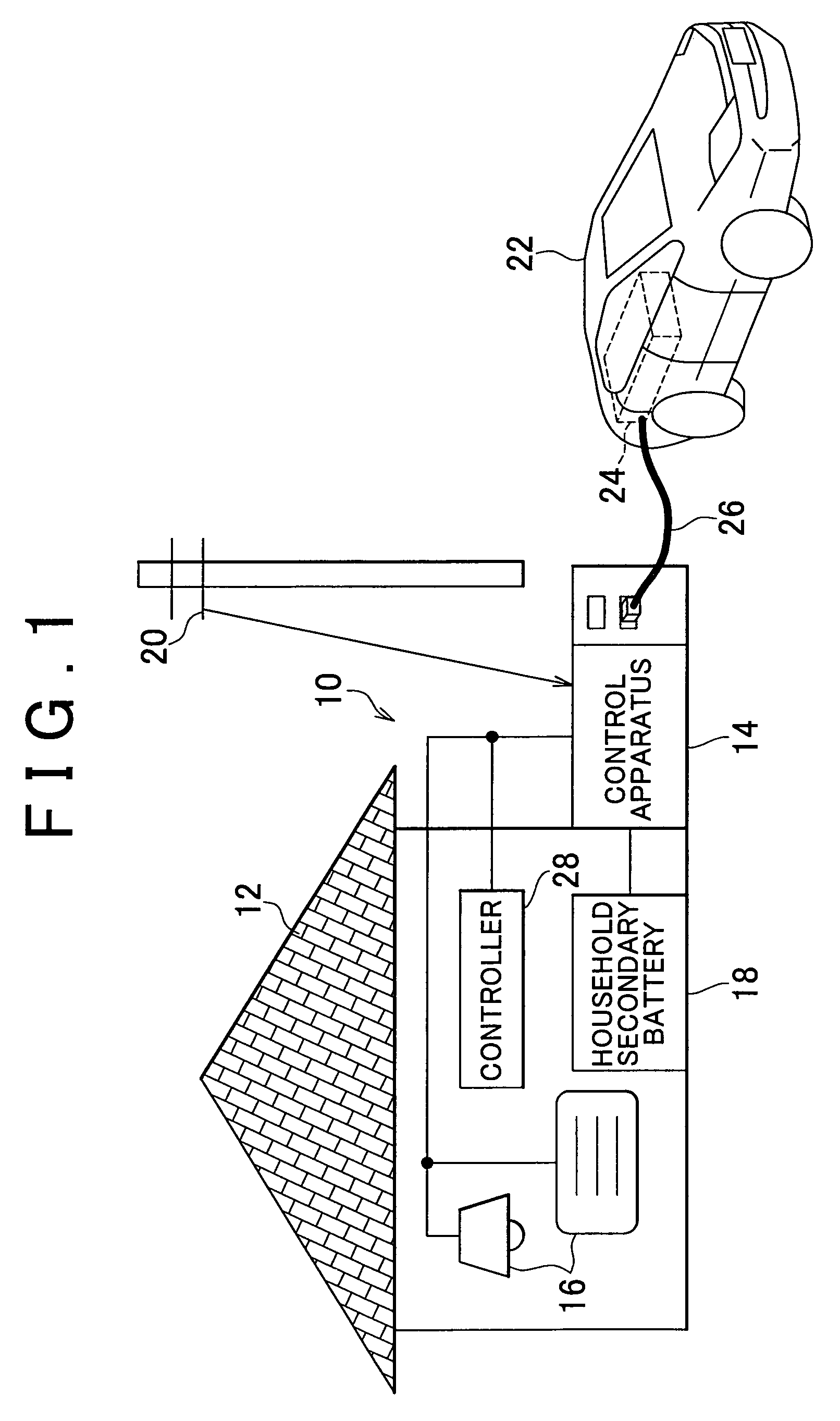
[0038]Example embodiments of the present invention will be described in greater detail below with reference to the accompanying drawings. FIG. 1 is a schematic diagram of an electric power supply system according to a first example embodiment of the invention.

[0039]The electric power supply system 10 according to this first example embodiment of the invention includes a control apparatus 14 that controls the supply of electric power used by a building 12 such as a house. Incidentally, in this example embodiment the building 12 is an individual house, but the invention is not limited to this. For example, the invention may also be applied to an apartment house or another type of building.

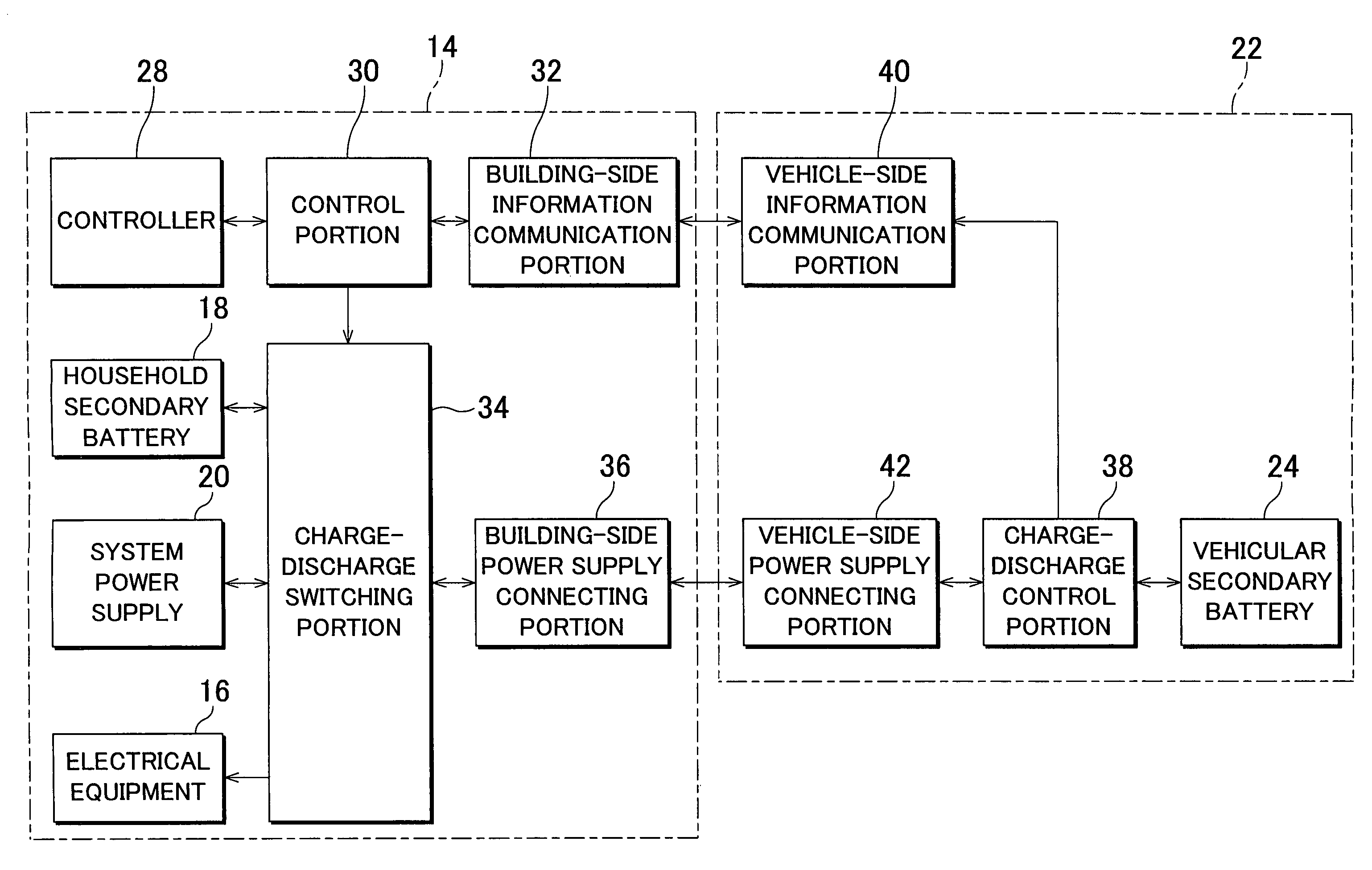
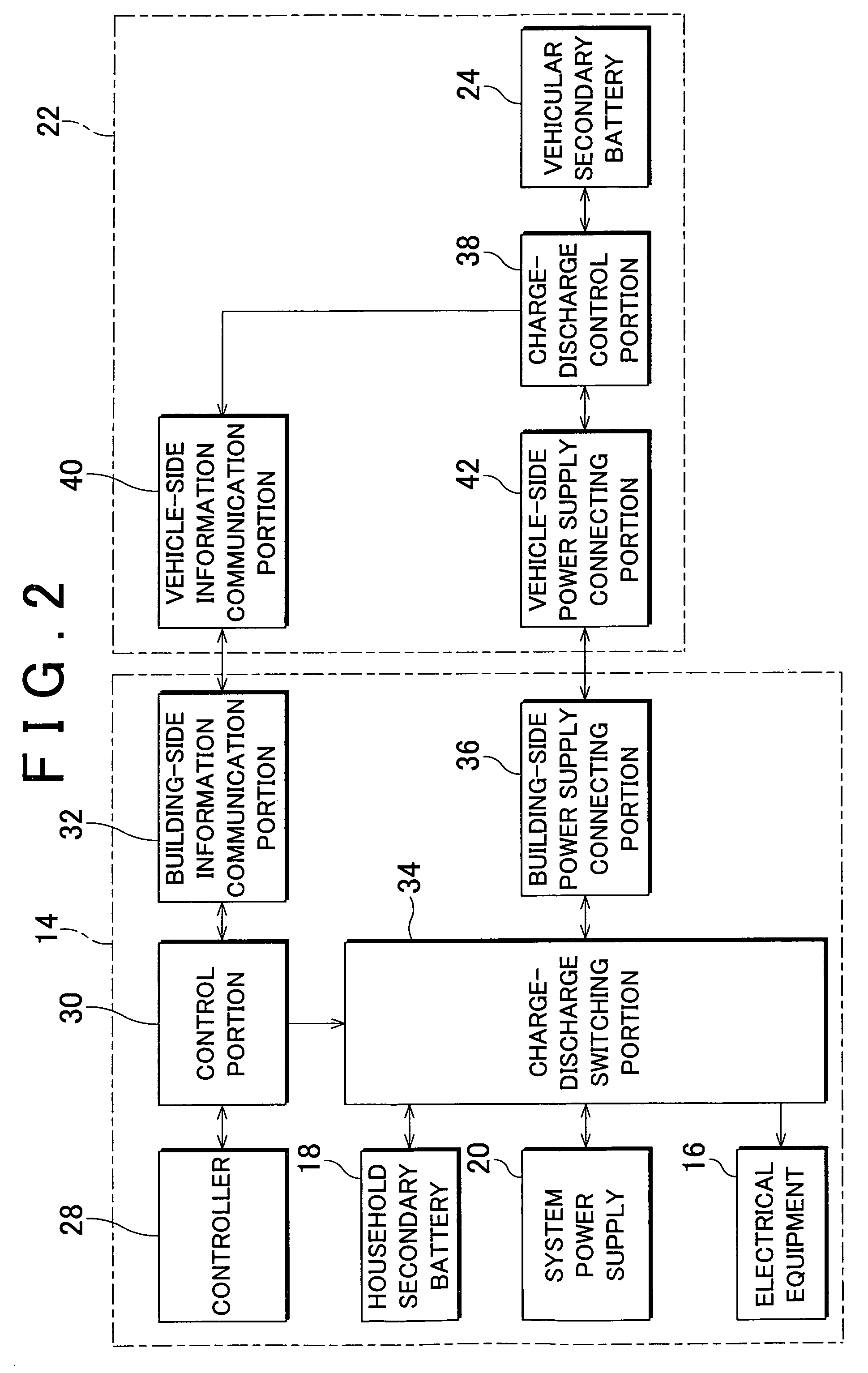
[0040]This control apparatus 14 is connected to electrical equipment (such as lighting equipment, an air-conditioner, and the like) 16 provided in the building 12, a household secondary battery 18 that stores electric power used by the building 12, and a system power supply 20, as well as to a vehicu...


PUM


Abstract

An electric power supply system includes a connecting device that connects a secondary battery provided in a vehicle to a building, and a control apparatus that i) identifies the type of the vehicle that is connected to the connecting device, the type of the secondary battery, or the type of electric power that is distinguishable by the charging source of the electric power stored in the secondary battery, ii) determines a preset electric power supply method based on the identification results, and iii) controls a supply of electric power from the secondary battery to the building based on the determined electric power supply method.

Description

CROSS-REFERENCE TO RELATED APPLICATIONS[0001]This application is the U.S. National Phase of PCT / IB2010 / 002124 filed Aug. 30, 2010, which claims priority of Japanese Patent Application 2009-199890 filed Aug. 31, 2009.BACKGROUND OF THE INVENTION[0002]1. Field of the Invention[0003]The invention relates to an electric power supply system, and more particularly, an electric power supply system and an electric power supply method that supplies electric power from a secondary battery provided in a vehicle to a building.[0004]2. Description of the Related Art[0005]In recent years, with the aim of reducing CO2 in an attempt to prevent global warming, hybrid vehicles that are provided with a secondary battery and use both an engine and a motor as a power source, have become increasingly popular, and electric vehicles that are provided with a secondary battery are also starting to receive attention.[0006]Moreover, technology for supplying electric power from a secondary battery provided in su...

Claims


Application Information

Patent Timeline
Patent Type & Authority Patents(United States)
IPC IPC(8): H02J7/00B60L11/18B60L50/16H02J3/38
CPCB60L11/1824B60L11/1816B60L11/1861H02J3/38Y02T10/7005Y02T10/7044Y02T10/705Y02T10/7088Y02T90/14Y02T90/121Y04S10/126Y02E60/721B60L2240/80B60L7/12B60L2250/16B60L2260/52B60L2260/54B60L2260/58Y02T10/70Y04S30/14B60L50/16B60L53/64B60L55/00B60L53/63B60L53/65B60L58/13B60L53/53B60L53/18B60L53/305B60L58/15Y02E60/00Y02T10/7072Y02T90/12Y02T90/167Y02T90/16B60L53/30
Inventor MURAWAKA, KATSUTOSHI
Owner TOYOTA JIDOSHA KK
Why Eureka
Try Eureka