
Printed circuit board

a printed circuit board and circuit board technology, applied in the direction of dc circuit to reduce harmonics/ripples, emergency protective circuit arrangements, multiple-port networks, etc., can solve the problems of high frequency switching noise, terminal noise or unwanted electromagnetic waves, and increase the imbalance between the two power supply lines, so as to reduce the common mode noise generated by the imbalance

Active Publication Date: 2015-05-26
CANON KK
View PDF7 Cites 3 Cited by
  • Summary
  • Abstract
  • Description
  • Claims
  • Application Information

AI Technical Summary

Benefits of technology

[0011]According to the present invention, imbalance between a pair of power supply lines by an excess current protection element can be corrected, and common mode noise generated by the imbalance can be reduced.
[0012]Further features of the present invention will become apparent from the following description of exemplary embodiments with reference to the attached drawings.

Problems solved by technology

However, in the power source circuit using the switching method, a switching operation generates a high frequency switching noise, and the noise causes terminal noise or unwanted electromagnetic waves.
Thus, if a switching frequency increases with decreasing size and increasing efficiency of the switching power source, an impedance by an inductance of the excess current protection element increases to increase imbalance between the two power supply lines.
If there is imbalance between the two power supply lines, a normal mode component of the high frequency noise flowing through the two power supply lines is converted into a common mode component, thereby increasing common mode noise.

Method used


Image

  • Printed circuit board
  • Printed circuit board
  • Printed circuit board

Examples


Embodiment Construction

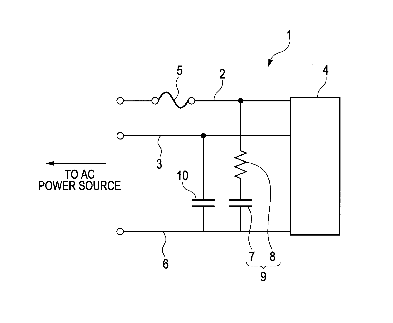
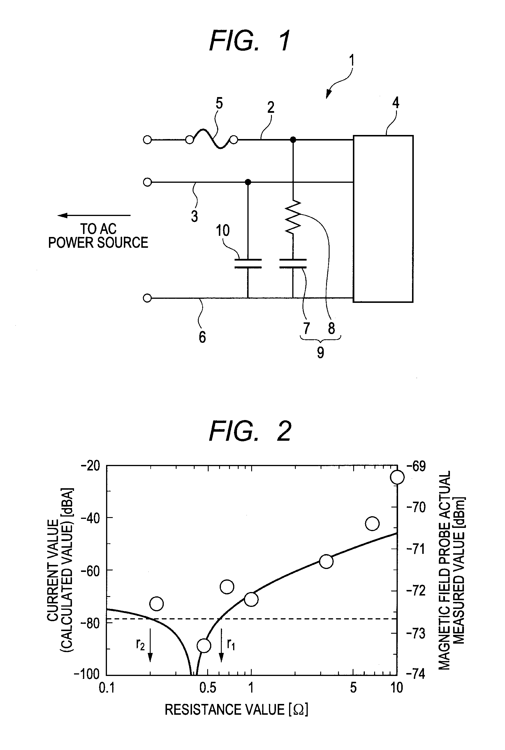
[0020]Now, an embodiment for carrying out the present invention will be described in detail with reference to the drawings. FIG. 1 is an electric circuit diagram illustrating a schematic configuration of a power source circuit according to the embodiment of the present invention. In FIG. 1, a power source circuit 1 includes a pair of power supply lines 2 and 3 connected to an alternating power source, and a switching circuit 4 as a power conversion circuit that converts an alternating voltage from an alternating power source input through the pair of power supply lines 2 and 3 into a direct current voltage. The alternating power source is, for example, a power source for commercial use. The switching circuit 4 includes, for example, a rectifying circuit having a bridge diode (not shown), a smoothing capacitor (not shown), and a DC-DC converter circuit (not shown) including a switching element. The rectifying circuit converts an alternating voltage into a direct current voltage, and ...


PUM


Abstract

A power source circuit includes a switching circuit 4 that converts a direct current voltage obtained by converting an alternating voltage from an alternating power source input through a pair of power supply lines 2 and 3 into a predetermined direct current voltage by a switching operation. A fuse 5 is provided on one power supply line 2. A series circuit 9 including a first line bypass capacitor 7 and a resistor element 8 is connected between one power supply line 2 and a ground 6. A second line bypass capacitor 10 is connected between the other power supply line 3 and the ground 6. Imbalance of the circuit by an excess current protection element is prevented to reduce common mode noise.

Description

TECHNICAL FIELD[0001]The present invention relates to a power source circuit that reduces a high frequency noise generated by a switching operation.BACKGROUND ART[0002]Conventionally, an electronic instrument includes a power conversion circuit for converting frequency or voltage of any input power source into those of a power source for various devices in the electronic instrument. In particular, a switching method is widely used for size reduction and higher efficiency. However, in the power source circuit using the switching method, a switching operation generates a high frequency switching noise, and the noise causes terminal noise or unwanted electromagnetic waves.[0003]As a noise filter that reduces such unwanted electromagnetic waves, PTL 1 discloses a line bypass capacitor (hereinafter referred to as a “Y capacitor”). FIG. 7 illustrates an example of a filter circuit used in a conventional switching power source circuit. The filter circuit 100 illustrated in FIG. 7 includes ...

Claims


Application Information

Patent Timeline
Patent Type & Authority Patents(United States)
IPC IPC(8): H02M1/12H02H7/125H02M1/44H03H7/38
CPCH02H7/1252H02M1/12H02M1/44H02M2001/123H03H7/38H02M1/123
Inventor IDE, TAKESHISEKIJIMA, DAISHIRO
Owner CANON KK
Learn More