Supercharge Your Innovation With Domain-Expert AI Agents!

Biometric voice command and control switching device and method of use

Active Publication Date: 2015-05-26
VOICE SECURITY SYST
View PDF20 Cites 19 Cited by
  • Summary
  • Abstract
  • Description
  • Claims
  • Application Information

AI Technical Summary

Benefits of technology

This patent describes a device and method for controlling electronic locks and doors using a biometric voice switch. The device can detect and reject background noise and successfully detect and reject unnatural spoken words. This eliminates the need for keys or cards and ensures security.

Problems solved by technology

The principal disadvantage is that it cannot operate in a self contained device and requires a network of terminals and a central processing station for authentication of an individual.
This teaches a method for locking a door with a voice command, but has the disadvantage of using a speaker independent voice recognition technology instead of biometric speaker verification technology making it unsuitable for unlocking the previously locked door from outside the secured space.
The disadvantage of a cadence based voice reference pattern is that it is not suitable for rejecting random background noise since it does not account for differences in the frequency domain, thus simply humming in the correct cadence would yield a positive result even though the correct phrase was not spoken.
This is one of many methods published for biometric acquisition and matching system, but does not define a method or apparatus for managing multiple commands and individuals or translating the verification results to an appropriate and useful output result.
The principal disadvantage is that the device is not useful for controlling a wide variety of external devices, but rather only the vehicle security system that contains the biometric acquisition module.
The disadvantage of this system is that it requires the individual to carry a magnetic card containing the identity of the individual which can be misplaced rendering the system unusable for that individual.
The disadvantage of this system is that it involves a two part verification which is inefficient and cumbersome to individuals using the system.
The disadvantage is that it can be used by anyone and cannot distinguish between different individuals and is therefore unsuitable for controlling access restriction devices (such as locks, etc.) and also is unable to provide administrative features restricted to a select group of authorized individuals.
The device disclosed also fails to intelligently switch between opposing states using a single, user selectable command.
The device also does not intelligently track a state to change switching behavior using the said single, user selectable command.
It also does not teach a method for using the system's verification result to offer administrative features to only a specific sub-set of authorized individuals.
This patent teaches one method for updating a previously stored speech reference pattern, but does so in a destructive manner.
The disadvantage of this system is that an update to the reference pattern acts on the reference data as a whole and does not preserve any of the original proven reference patterns.
Developing a solution of this type is not without challenges, some of which do not have obvious solutions.
However, the prior art does not teach the design of a host electronic hardware device capable of controlling a wide variety of external devices, nor does it provide the necessary user interface and device management facilities.

Method used


Image

  • Biometric voice command and control switching device and method of use
  • Biometric voice command and control switching device and method of use
  • Biometric voice command and control switching device and method of use

Examples


second embodiment

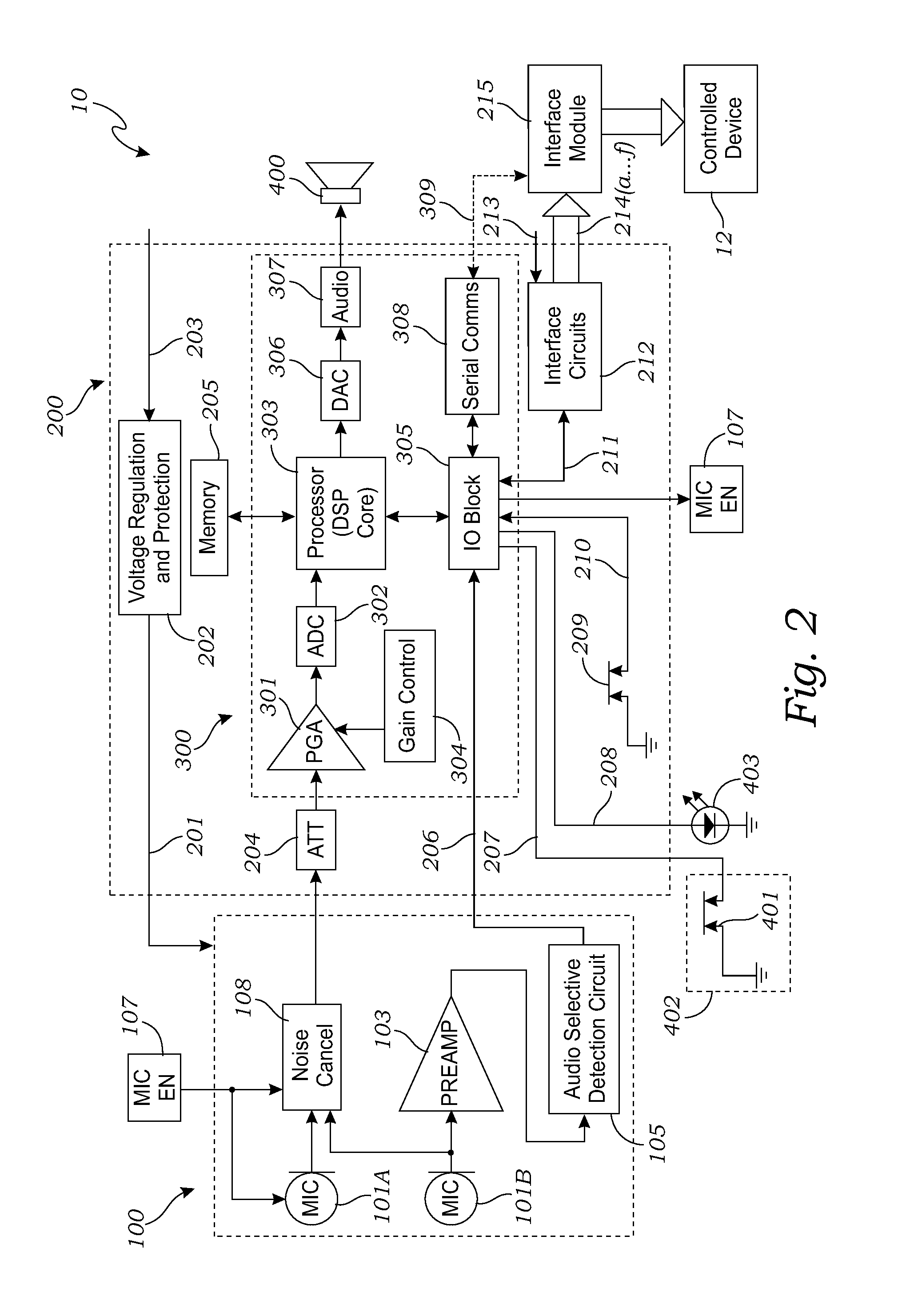
[0056]FIG. 2 is a block diagram of the biometric voice command and control switching device 10, wherein the microphone assembly 100 includes two microphones 101A and 101B, and a noise cancellation circuit 108. In the embodiment of FIG. 2, the first microphone 101A is operably connected to the processing device 200 through the noise cancellation circuit 108. The second microphone 101B is operably connected to the audio selective detection circuit 105, and also to the noise cancellation circuit 108. The first microphone 101A and the noise cancellation circuit 108 are both operably controlled by the microphone enable signal 107 from the processor 303.

[0057]In this configuration, the processor 303 may turn off the first microphone 101A and the noise cancellation circuit 108, to save power until the device 10 is activated. The second microphone 101B is left ready to receive the audio trigger and transmit it to the audio selective detection circuit 105, for switching on the device 10.

[005...

third embodiment

[0059]FIG. 3 is a block diagram of the biometric voice command and control switching device 10 that includes a microphone system 110 that includes multiple microphone assemblies 100 (in this case, two, 100A and 100B, although other numbers of microphone assemblies may be used. Each assembly may or may not include noise cancelling technology. The two microphone assemblies 100A and 100B are combined with a combiner 112. The term “combiner” is hereby defined to include any form of combining device that functions as described herein. The combiner 112 combines the output signals from the microphones, and routes power and control signals to all devices.

[0060]As illustrated in FIG. 3, the combiner 112 is operably attached to the voice processing unit 300, and enables the receipt of utterances as discussed above. The combiner 112 may also be operatively connected with the processor 303 to receive a microphone enable signal 107 for operatively initiating the combiner 112 (and / or noise cancel...


PUM


Abstract

A biometric voice command and control switching device has a microphone assembly for receiving a currently spoken challenge utterance and a reference utterance, and a voice processing circuit for creating electronic signals indicative thereof. The device further includes a memory for storing the electronic signals, and a processor for comparing the electronic signals to determine if there is a match. If there is a match, an interface circuit enables the operable control of the controlled device.

Description

CROSS-REFERENCE TO RELATED APPLICATIONS[0001]Not ApplicableSTATEMENT REGARDING FEDERALLY SPONSORED RESEARCH[0002]Not ApplicableBACKGROUND OF THE INVENTION[0003]1. Field of the Invention[0004]The invention disclosed herein relates generally to electronic switching devices which also provide for biometric acquisition and comparison of human voice patterns, in order to distinguish between individuals and perform a switching action or command by other digital communication means that communicates with and controls another external device when a successful match is made between a live utterance sample and stored biometric patterns.[0005]2. Description of Related Art[0006]The following patents form a background for the instant invention. None of the cited publications is believed to detract from the patentability of the claimed invention.[0007]Hair et al., U.S. Pat. No. 3,673,331, describes voice verification that is accomplished at a plurality of spaced apart facilities each having a plu...

Claims


Application Information

Patent Timeline
IPC IPC(8): G10L21/00G10L15/183G10L15/30
CPCG10L15/30G10L15/183G06F21/32G10L17/24
Inventor ADCOCK, SHERRIEROBINSON, KENTCLEMENTS, BRADBROCKELSBY, MARK KEITHBROCKELSBY, WILLIAM KEITH
Owner VOICE SECURITY SYST
Features
  • R&D
  • Intellectual Property
  • Life Sciences
  • Materials
  • Tech Scout
  • Unparalleled Data Quality
  • Higher Quality Content
  • 60% Fewer Hallucinations
Learn More