Windscreen wiper device

a technology of wiper arm and windscreen, which is applied in the direction of vehicle cleaning, dynamo-electric machines, electrical apparatus, etc., can solve the problems of delay in the wiping cycle, unfavorable extension of the time required for a complete wiping cycle of the wiper arm on the windscreen,

Active Publication Date: 2015-06-02
ROBERT BOSCH GMBH
View PDF14 Cites 21 Cited by
  • Summary
  • Abstract
  • Description
  • Claims
  • Application Information

AI Technical Summary

Benefits of technology

[0005]It is therefore the object of the present invention to provide a windscreen wiper device, control of which allows optimum adaptation to the actual torque demand of the windscreen wiper device with simultaneous minimum load on the system and which at the same time enables the oscillating wiping movement of the wiper arm on the windscreen to be as uniform as possible.

Problems solved by technology

Thus an undesirable extension of the time required for a complete wiping cycle of the wiper arm on the windscreen can be countered.
If the motor voltage or torque were reduced shortly before reaching the operating speed, the motor—even without additional load such as snow and ice—would, during the start-up phase after passing through a turning point, lack the power to overcome its own inertia and reach its desired nominal speed, which would also lead to a delay in the wiping cycle.

Method used


Image

  • Windscreen wiper device
  • Windscreen wiper device
  • Windscreen wiper device

Examples


Embodiment Construction

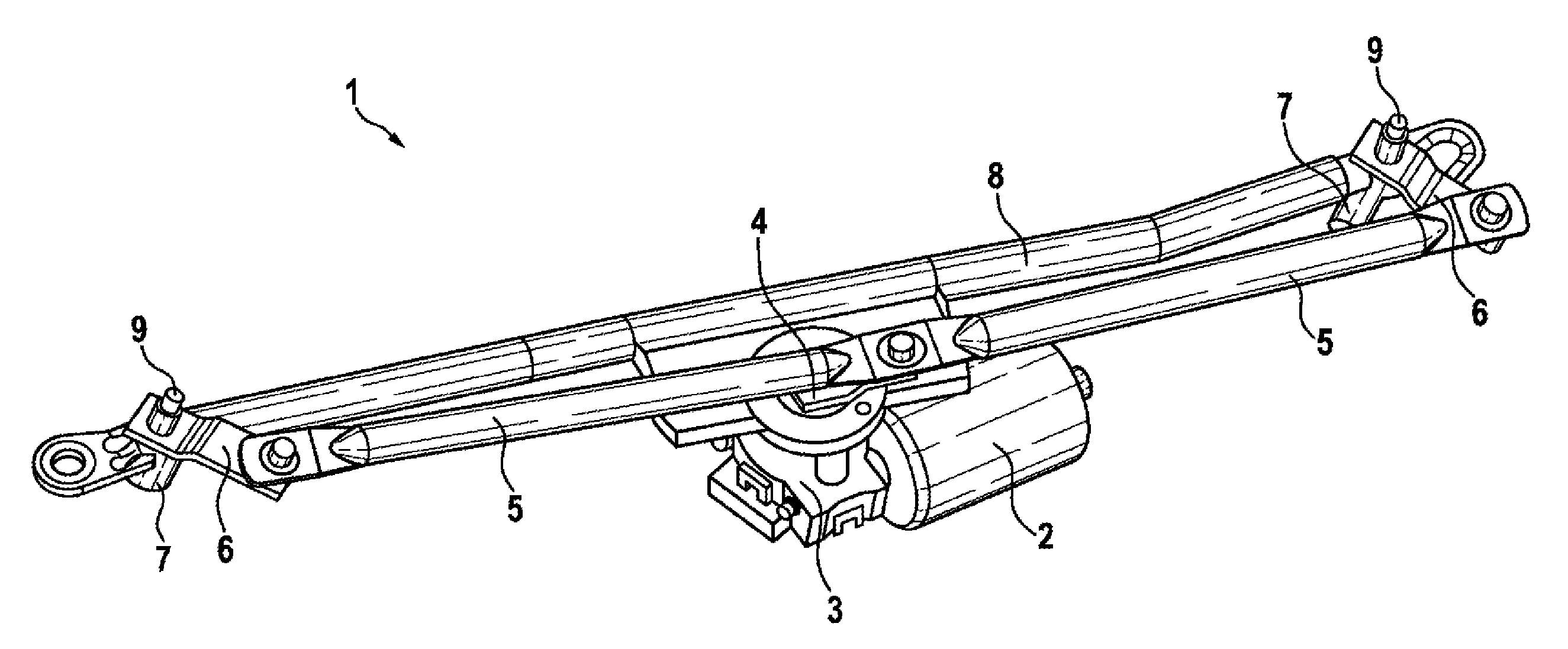
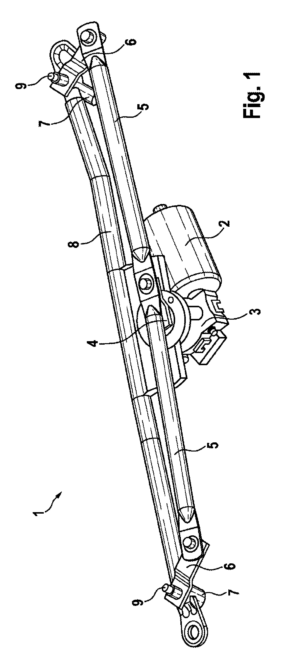
[0024]FIG. 1 shows a perspective view of a windscreen wiper device. The windscreen wiper device 1 essentially comprises a wiper motor 2 which via a gearing 3—not shown in more detail—drives an output shaft. The output shaft is connected rotationally fixed with a motor crank 4 which transfers the torque it receives to two connecting rods 5. The connecting rods 5 are connected rotationally mobile at their one end with the free end of the crank 4 and at their other end via an output crank 6 with a wiper bearing 7.

[0025]The wiper bearings 7 in turn are connected together via a tube plate 8. The wiper bearings 7 each have a wiper shaft 9 which carries wiper arms with wiper blades not shown here. The output cranks 6 are connected rotationally fixed with the wiper bearings 7 or wiper shafts 9 so that a thrust movement of the connecting rods 5 is translated into an oscillating rotary movement via the output cranks 6 at the wiper shafts 9.

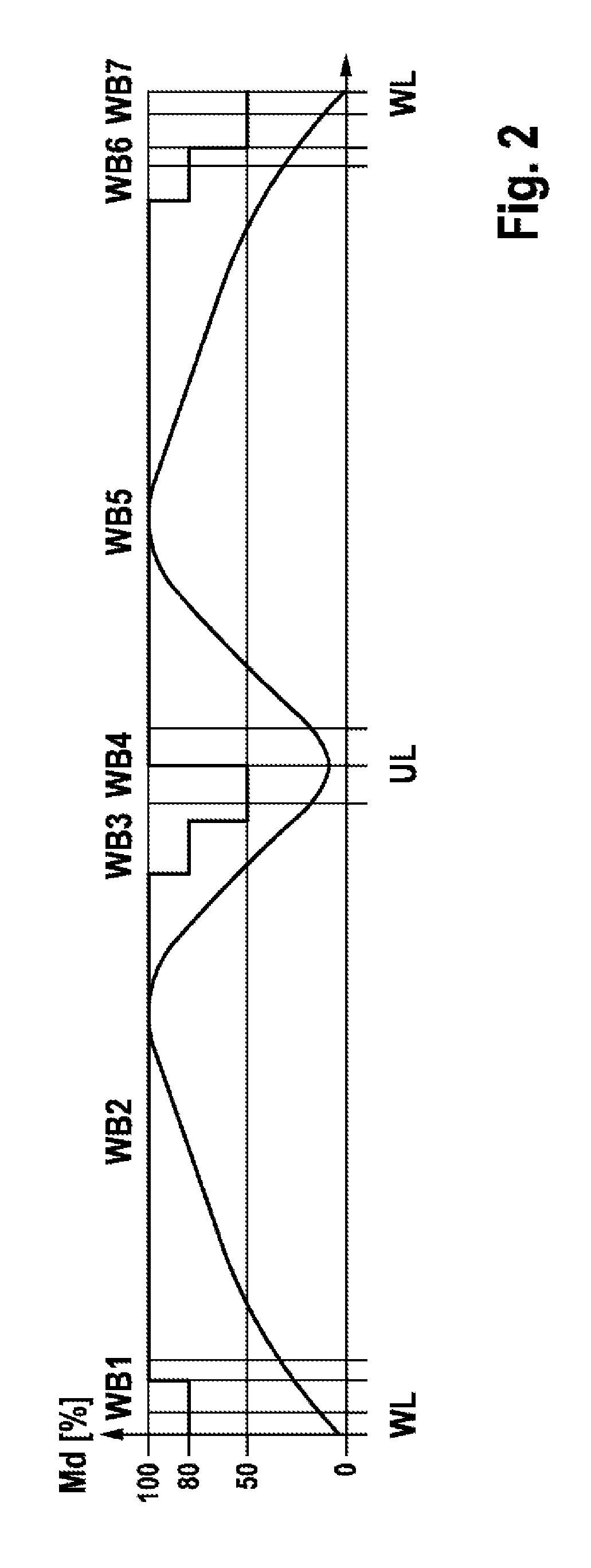
[0026]FIG. 2 shows a diagram of the torque demand and...


PUM


Abstract

A windscreen wiper device (I) for a motor vehicle. The device includes at least one wiper motor (2) on which a motor crank (4) is provided connected to at least one gearing (3) which is downstream of said wiper motor (2), so as to drive a wiper arm that is coupled thereto such that said arm performs an oscillating wiper movement on a windscreen of said motor vehicle, said wiper motor (2) being coupled to a control unit. Motor power generated by the wiper motor (2) is adjusted by the control unit depending on a transmission ratio which results from the position of said gearing (3). The control unit delays a reduction in the motor power until after the motor crank (4) has accelerated out of the respective wiper arm turning points to produce as uniform a wiper arm movement as possible on the windscreen.

Description

BACKGROUND OF THE INVENTION[0001]The present invention concerns a windscreen wiper device for a motor vehicle with at least one wiper motor, in particular a reversing motor, on which is provided a motor crank which is connected with at least one gearing connected downstream of the wiper motor in order to drive a wiper arm coupled therewith such that it executes an oscillating wiping movement on a windscreen of the motor vehicle, wherein the wiper motor is coupled with a control unit to control the wiping movement, by means of which unit a motor power generated by the wiper motor can be adjusted as a function of a position of the gearing or wiper arm on the windscreen. The invention furthermore concerns a method for controlling the windscreen wiper device.[0002]Such a windscreen wiper device is known for example from document DE 101 44 985 A1. This document discloses a method to control a windscreen wiper device in which the motor power of the wiper motor is controlled as a function ...

Claims


Application Information

Patent Timeline
Patent Type & Authority Patents(United States)
IPC IPC(8): H02K33/00B60S1/08
CPCB60S1/08
Inventor ZIMMER, JOACHIM
Owner ROBERT BOSCH GMBH
Why Eureka
Try Eureka