Check patentability & draft patents in minutes with Patsnap Eureka AI!

Latching over-current protection circuit and method

a protection circuit and over-current technology, applied in the field of current limiting protection circuits, can solve the problems of high power rating of load current switching transistors and/or easy failur

Active Publication Date: 2015-06-02
JOHNSON CONTROLS TYCO IP HLDG LLP
View PDF8 Cites 3 Cited by
  • Summary
  • Abstract
  • Description
  • Claims
  • Application Information

AI Technical Summary

Benefits of technology

The invention is a circuit and method for controlling the current provided to a load. This is done through a transistor switch and a latching circuit that can turn off the transistor switch in the event of an over-current condition. The circuit includes a current sensing transistor that can trigger the latching circuit. An external controller can turn the transistor switch on or off and be alerted of an over-current condition. The technical effect of the invention is to provide a circuit and method for protecting the load from over-current conditions, and to provide a means for controlling the current to the load.

Problems solved by technology

This requires the load current switching transistor to dissipate a large amount of power, which in turn, requires the load current switching transistor to have a high power rating and / or to be prone to failure.

Method used


Image

  • Latching over-current protection circuit and method
  • Latching over-current protection circuit and method
  • Latching over-current protection circuit and method

Examples


Embodiment Construction

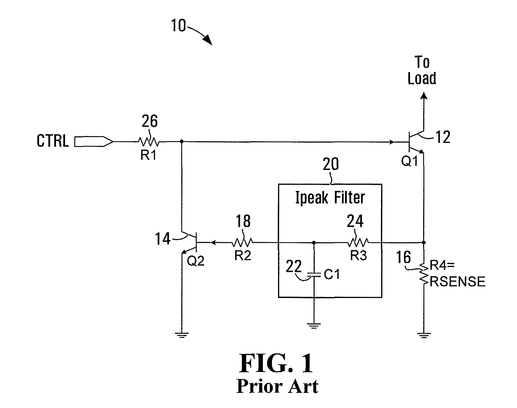
[0012]FIG. 1 illustrates a conventional current limiting circuit 10 formed of two bipolar junction transistors (BJT) Q112, and Q214. A control input CTRL drives the base of Q112. Q112 acts to switch the load current. A resistor R416 connects the emitter of Q112 to ground. The node between the emitter of Q112 and R416 is interconnected to a filter 20 formed of C122 and R324. The output of filter 20 is interconnected to the base of Q214 by way of a resistor R218. Both Q112 and Q214 are configured as switches, or operating in their linear region, controlled by a voltage applied to their base in case of an over current condition.

[0013]A small control voltage (e.g. 3.3V—equivalent to a logic HI) may be applied to CTRL by an external controller, thereby applying a voltage to the base of Q112. If Q214 is off (high impedance between collector and emitter), this turns on Q112, and a load current from an external source is provided through the collector of Q112 to an external load (not shown)...


PUM


Abstract

A load limiting circuit includes a transistor switch, for providing current to a load and a latching circuit having a control input, and a latch output driving the transistor switch. A current sensing transistor interconnects with the transistor switch, to sense current in excess of a threshold to the load. The current sensing transistor drives the control input to the latching circuit. An external controller may drive and monitor the control input. The controller may thus turn the transistor switch on and off, and be notified of an over-current condition. The latching circuit may turn the transistor switch off permanently. As well, the controller may attempt to set the load limiting circuit after an over-current condition.

Description

CROSS-REFERENCE TO RELATED APPLICATIONS[0001]The present application claims priority from U.S. Provisional Patent Application No. 61 / 577,303, filed Dec. 19, 2011 the contents of which are hereby incorporated by reference.FIELD OF THE INVENTION[0002]The present invention relates generally to electronic circuits and devices, and more particularly to a current limiting protection circuit whose state can be latched.BACKGROUND OF THE INVENTION[0003]Over-current protection for electrical loads is common place. To this end, transistor based current limiting circuits are well known.[0004]In one such circuit, a transistor is used as a switch to switch current to a load. In the presence of a sensed over-current condition, a further transistor switch is turned on, in order to turn off the load current switching transistor. As explained below, as the load impedance, the voltage across the load current switching transistor increases in order to maintain a constant current. This requires the load...

Claims


Application Information

Patent Timeline
Patent Type & Authority Patents(United States)
IPC IPC(8): G05F1/56G01R19/00G01R23/02G06F17/00H02H3/06H02H3/087H02J7/00
CPCG01R23/02G01R19/00G06F17/00H02H3/087H02J7/0068H02H3/06G01R19/003G01R19/02G01R19/04G01R19/16528G01R19/16576F16H59/105G01D5/2457G01B7/003G01B7/14
Inventor BUCSA, ANDREIFOSTY, STEPHEN D. W.
Owner JOHNSON CONTROLS TYCO IP HLDG LLP
Features
  • R&D
  • Intellectual Property
  • Life Sciences
  • Materials
  • Tech Scout
  • Unparalleled Data Quality
  • Higher Quality Content
  • 60% Fewer Hallucinations
Learn More