
Optical pickup device, optical information device, and information processing device

a pickup device and optical information technology, applied in the direction of data recording, instruments, disposition/mounting of heads, etc., can solve the problems of insufficient light spot focusing performance, wavefront aberration is needed, and the specifications of optical pickup devices have become increasingly severe, so as to reduce the device cost, stable high-density recording and reproduction, and good focusing characteristics

Inactive Publication Date: 2015-06-02
PANASONIC INTELLECTUAL PROPERTY MANAGEMENT CO LTD
View PDF20 Cites 0 Cited by
  • Summary
  • Abstract
  • Description
  • Claims
  • Application Information

AI Technical Summary

Benefits of technology

[0024]It is an object of the present invention to provide an optical pickup device, an optical information device, and an information processing device that make it is possible to obtain a good focusing characteristic, realize stable high-density recording and reproduction, reduce the device cost, and reduce the device in size and thickness by using a single objective lens compatible with disk-shaped recording media of a plurality of types.
[0026]With the above-described optical pickup device, it is possible to obtain a good focusing characteristic, realize stable high-density recording and reproduction, reduce the device cost, and reduce the device in size and thickness by using a single objective lens compatible with disk-shaped recording media of a plurality of types.

Problems solved by technology

A high-performance objective lens with a small wavefront aberration is needed, and specifications required for optical pickup devices have become increasingly severe.
In particular, in compatible optical pickup devices suitable for using a plurality of standards, namely, the high-density and high-capacity BD and also the conventional optical disks such as DVD, temperature compensation of spherical aberration and astigmatism of objective lenses is difficult, and the demand for optical pickup devices with small spherical aberration and astigmatism caused by temperature changes, that is, with good temperature characteristic, has grown.
The resultant problem is that sufficient light spot focusing performance cannot be obtained due to defocusing, and the system is not suitable for high-density recording and reproduction.
The resultant problem is that the lens holder 121 is increased in size and the optical pickup device is also increased in size.

Method used


Image

  • Optical pickup device, optical information device, and information processing device
  • Optical pickup device, optical information device, and information processing device
  • Optical pickup device, optical information device, and information processing device

Examples


embodiment 1

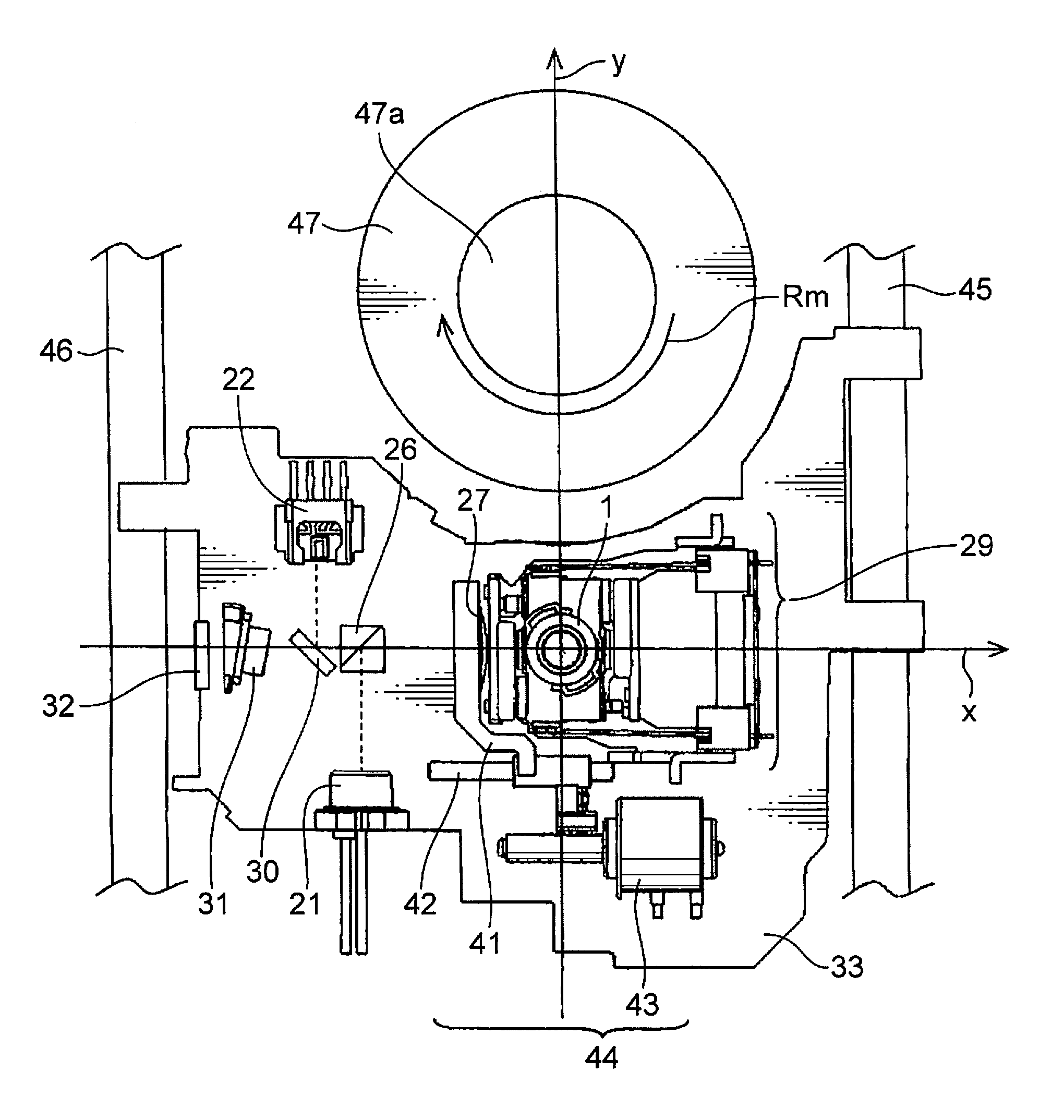
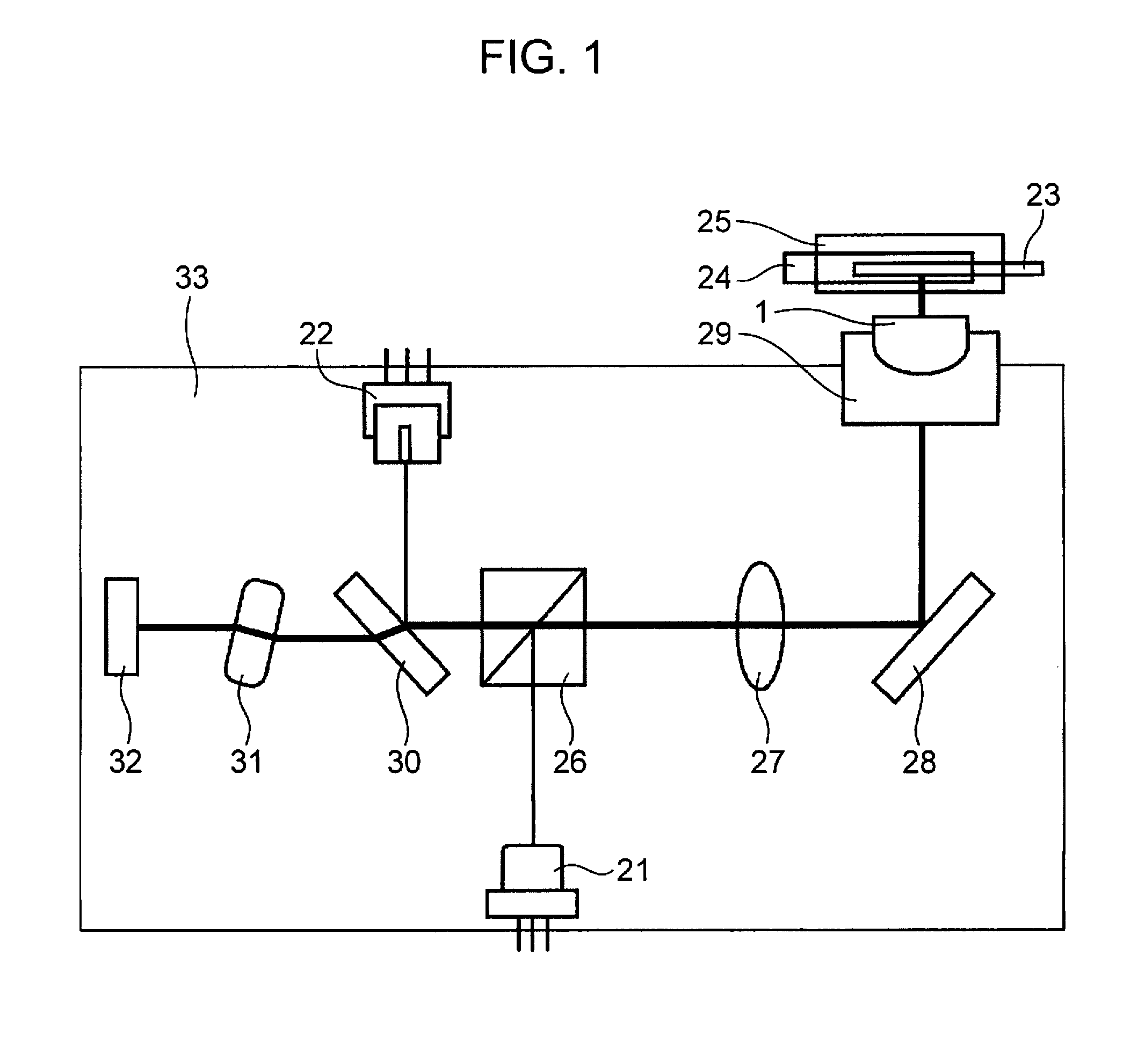
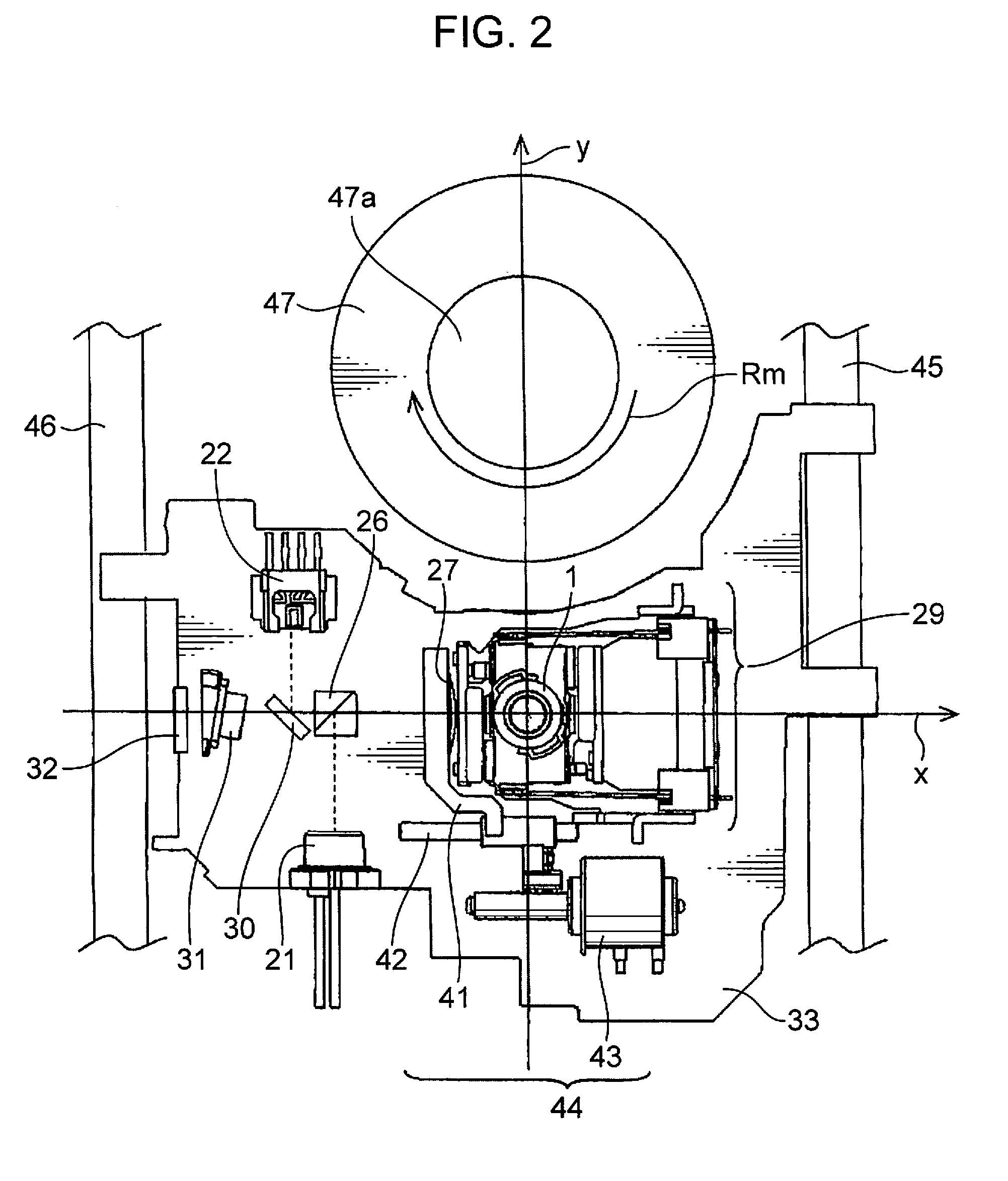
[0060]FIG. 1 is a schematic diagram illustrating the schematic configuration of the optical pickup device according to Embodiment 1 of the present invention. FIG. 2 is a top view illustrating the specific configuration of the optical pickup device shown in FIG. 1.

[0061]The optical pickup device shown in FIGS. 1 and 2 includes an objective lens 1, a blue semiconductor laser unit 21, a red and infrared semiconductor laser unit 22, a beam splitter 26, a collimator lens 27, a mirror 28, an objective lens actuator 29, a plate beam splitter 30, a detection lens 31, a photodetector 32, and an optical base 33. Further, as shown in FIG. 2, the optical pickup device is also provided with a CL (collimator lens) actuator 44. The CL actuator 44 includes a CL holder 41, a CL actuator spindle 42, and a stepping motor 43.

[0062]In FIGS. 1 and 2, the blue semiconductor laser unit 21 is held at the optical base 33. A light beam emitted from the blue semiconductor laser unit 21 has a wavelength of 400 ...

embodiment 2

[0122]The optical pickup device of Embodiment 2 of the present invention is described below. FIG. 7 is a perspective view illustrating the configuration of the objective lens actuator of the optical pickup device in Embodiment 2 of the present invention. FIG. 8 is a top view illustrating the configuration of the objective lens actuator shown in FIG. 7. FIG. 9 is a perspective view illustrating the configuration of the movable body of the objective lens actuator shown in FIG. 7. FIG. 10 is a perspective view illustrating the configuration of magnets and coils of the objective lens actuator shown in FIG. 7.

[0123]The optical pickup device of the present embodiment is configured similarly to the optical pickup device shown in FIGS. 1 and 2, except that the objective lens actuator 29 shown in FIGS. 1 and 2 is replaced with the objective lens actuator 29′ shown in FIG. 7. Therefore, graphic representation of the entire configuration is herein omitted and the explanation is performed with ...

embodiment 3

[0173]FIG. 14 illustrates an embodiment of an optical disk device which is an example of an optical information device using the optical pickup device of the above-described Embodiment 1 or Embodiment 2. FIG. 14 is a schematic diagram illustrating the schematic configuration of the optical disk device in Embodiment 3 of the present invention. Referring to FIG. 14, an optical disk device 607 is provided with a drive device 601, an optical pickup device 602, an electric circuit 603, a motor 604, a turntable 605, and a clamper 606.

[0174]Referring to FIG. 14, the optical disk 200 is placed on the turntable 605, held by the damper 606, and rotated by the motor 604. The optical pickup device 602 shown in Embodiment 1 or 2 is transferred by the drive device 601 to a position on the optical disk 200 where the desired information is present.

[0175]The electric circuit 603 is an example of a control unit that controls the optical pickup device 602 and the motor 604 on the basis of the signal o...


PUM

PropertyMeasurementUnit
wavelengthaaaaaaaaaa

Abstract

An optical pickup device includes a single objective lens that focuses a light beam to irradiate an optical disk, and an objective lens actuator that drives the objective lens. The objective lens actuator includes a lens holder that holds the objective lens. Two gaps (Ga, Gb) are formed between the lens holder and the objective lens. In an xy plane in which the center of the objective lens is defined as an origin, the tracking direction is defined as an y axis, and the tangential direction of tracks of the optical disk is defined as an x axis, the gap (Ga) is positioned at least in the first quadrant of the xy plane, and the gap (Gb) is positioned at least in the third quadrant of the xy plane.

Description

BACKGROUND OF THE INVENTION[0001]1. Technical Field[0002]The present invention relates to an optical pickup device that records and / or reproduces information on / from a disk-shaped recording medium, an optical information device using the optical pickup device, and an information processing device using the optical information device.[0003]2. Background Art[0004]Various optical pickup devices for reproducing and recording information from and to CD (compact discs) and DVD (digital versatile discs), which are optical disks representing the conventional disk-shaped recording medium, and recently on BD (Blu-ray Discs) have been developed, manufactured and widely spread.[0005]The wavelength of the light source used in CD or DVD is about 780 nm and about 660 nm, whereas a BD is an optical disk of a high-density and high-capacity type that uses a laser light source with the so-called blue-violet light having a wavelength of about 405 nm as a light source. In the case of such an optical dis...

Claims


Application Information

Patent Timeline
Patent Type & Authority Patents(United States)
IPC IPC(8): G11B7/00G11B7/09G11B7/1353G11B7/1374G11B7/1392
CPCG11B7/0908G11B7/0935G11B7/1374G11B7/1353G11B7/13922G11B2007/0006
Inventor WAKABAYASHI, KANJIIEKI, KOUJI
Owner PANASONIC INTELLECTUAL PROPERTY MANAGEMENT CO LTD
Learn More