Power supplying system, monitoring apparatus, monitoring method and computer program
a technology of power supply system and monitoring apparatus, applied in the direction of data switching network, data switching details, instruments, etc., can solve the problems of inability to obtain accurate information when monitoring either signal information or power, and no means of monitoring operation sta
- Summary
- Abstract
- Description
- Claims
- Application Information
AI Technical Summary
Benefits of technology
Problems solved by technology
Method used
Image
Examples
first embodiment
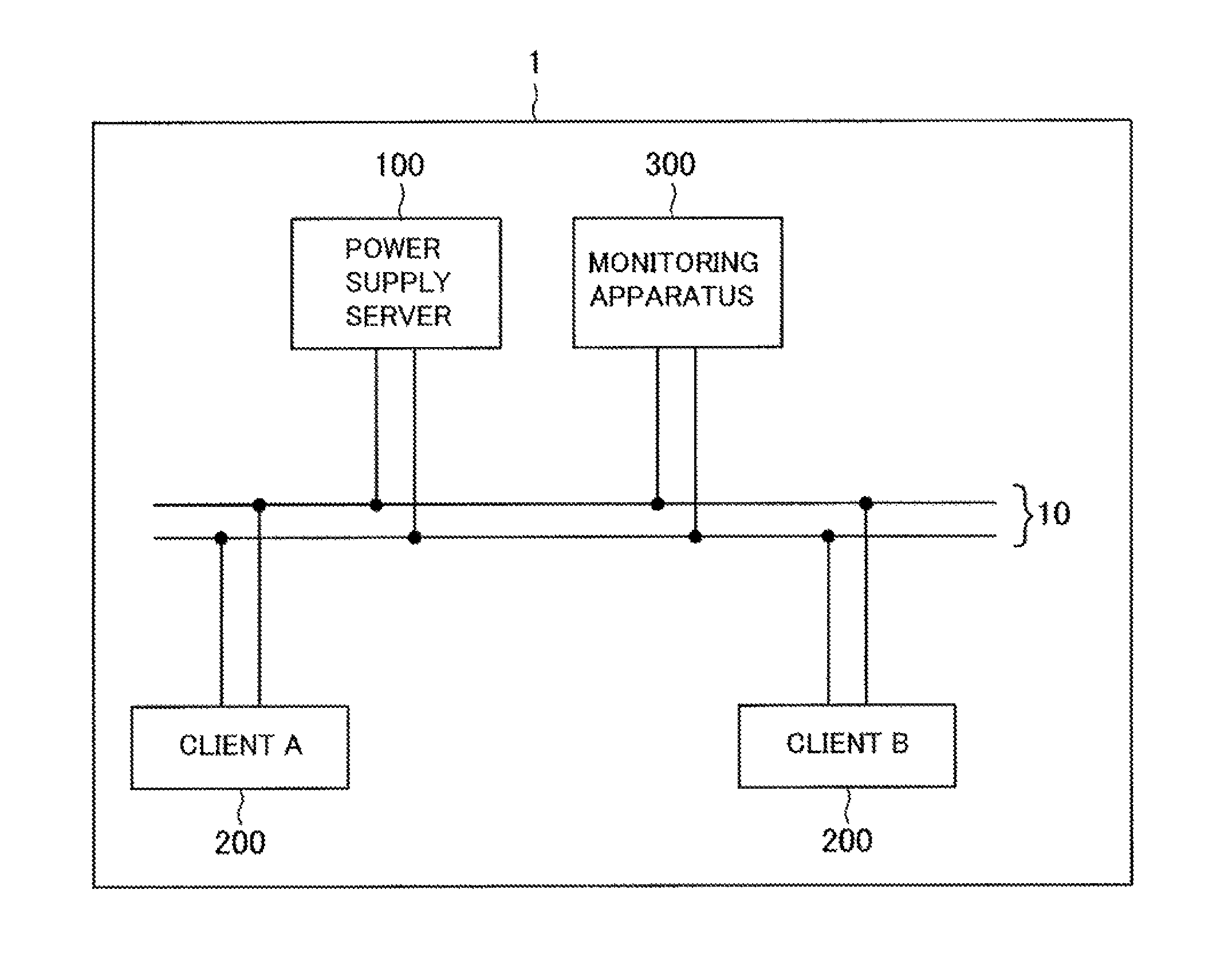
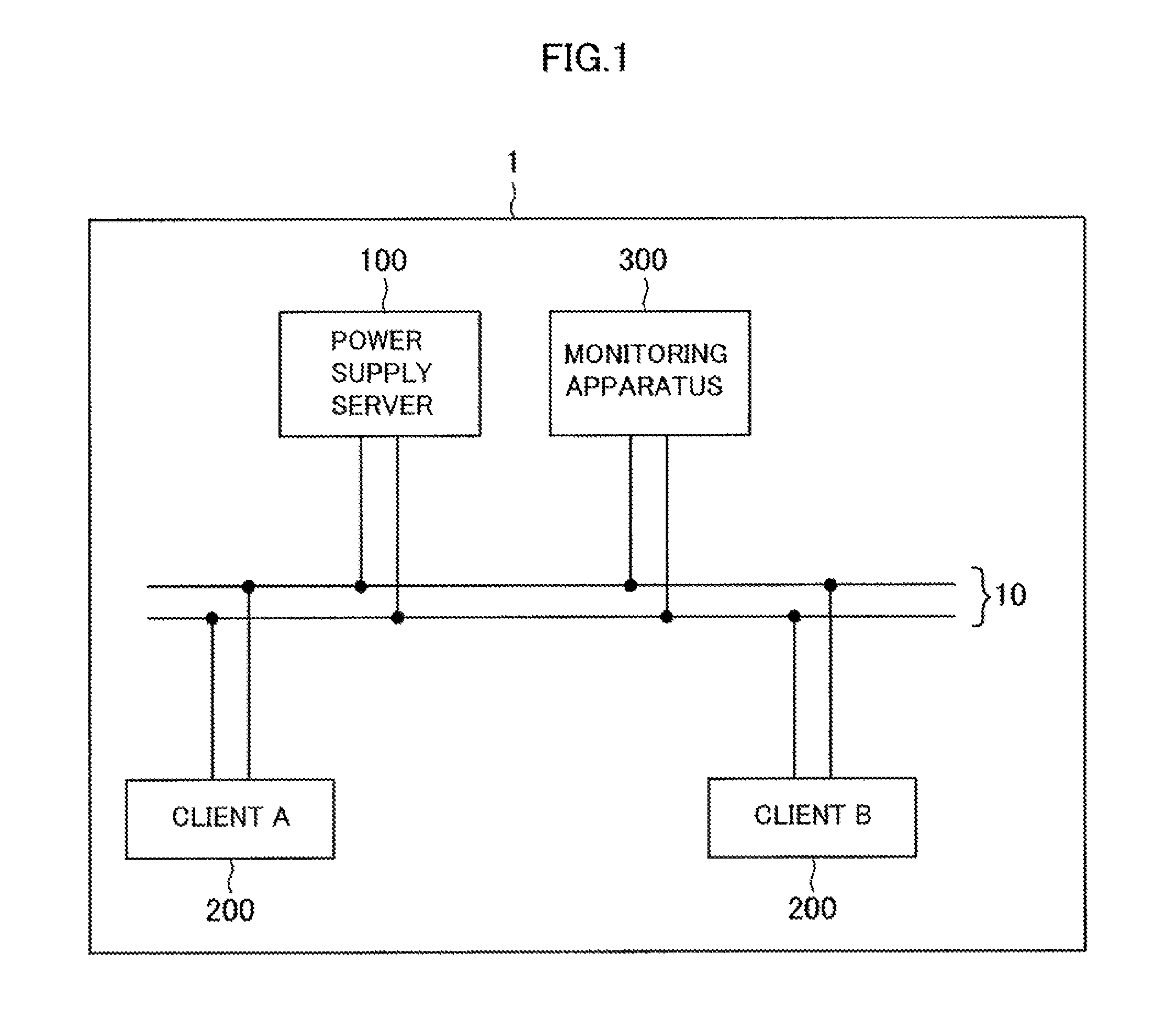
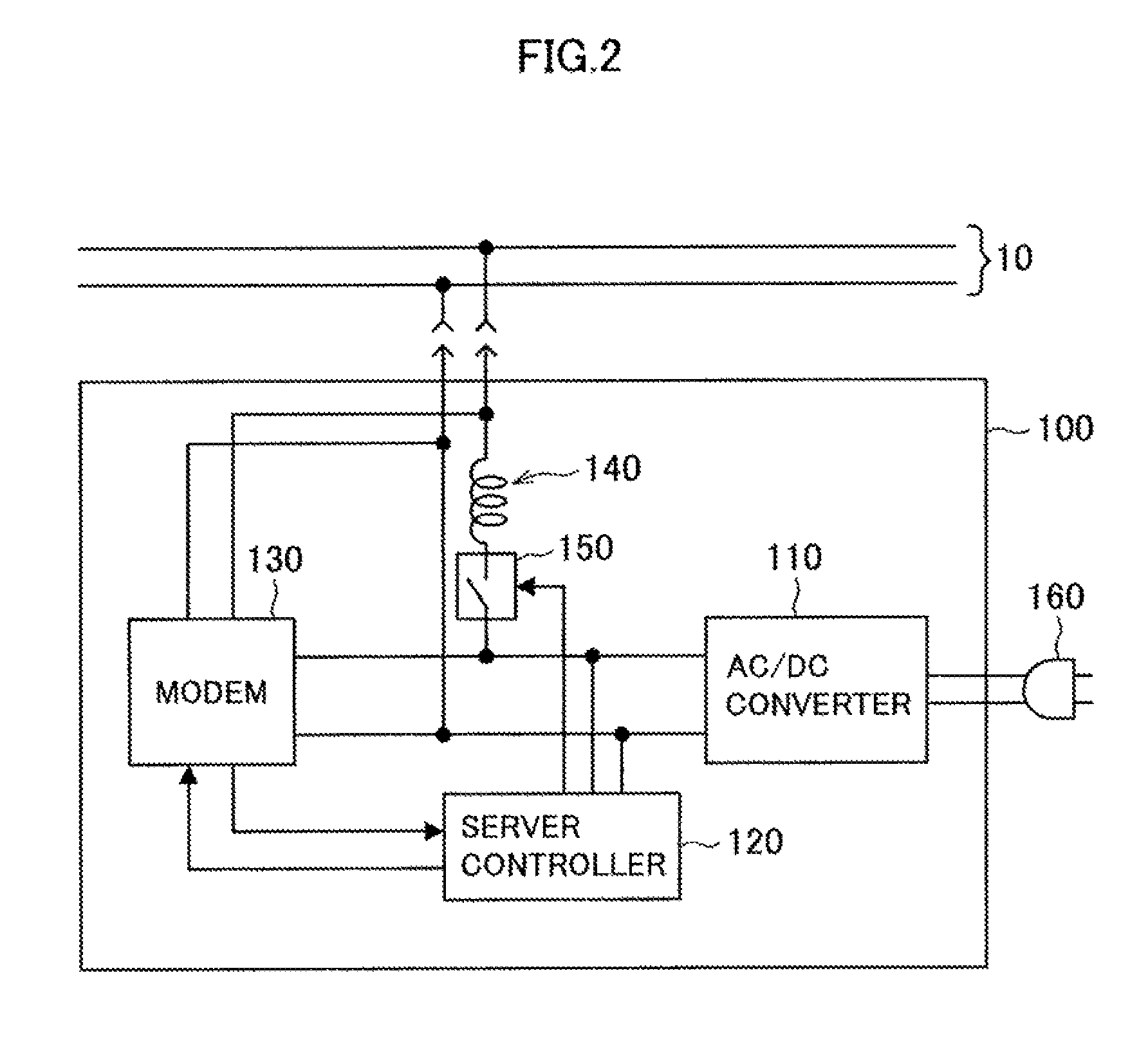
[0039]The configuration of a power supplying system 1 according to a first embodiment of the present invention is described hereinafter with reference to FIGS. 1 to 4. FIG. 1 is an explanatory view showing the schematic configuration of the power supplying system 1 according to the embodiment. FIG. 2 is an explanatory view showing the configuration of a power supply server 100 according to the embodiment. FIG. 3 is an explanatory view showing the configuration of a client according to the embodiment. FIG. 4 is an explanatory view showing the configuration of a monitoring apparatus according to the embodiment.
[0040]In the power supplying system 1 according to the embodiment, a power supply server 100, a client 200 and a monitoring apparatus 300 are connected to one bus line 10 as shown in FIG. 1. Although one power supply server 100, two clients 200 and one monitoring apparatus 300 are connected through the bus line 10 in this embodiment, one or two or more power supply servers 100, ...
second embodiment
[0077]A power supplying system according to a second embodiment of the present invention is described hereinafter with reference to FIGS. 8 to 10. In the power supplying system of this embodiment, the power supply server 100, the client 200 and the monitoring apparatus 300 are connected through the bus line 10 as shown in FIG. 1, just like the first embodiment. However, the monitoring apparatus 300 of this embodiment is capable of exchanging an information signal with the power supply server 100 and the client 200, which is different from the first embodiment.
[0078]The display processing of an information signal by the monitoring apparatus 300, which is different from that of the first embodiment, is described hereinbelow. FIG. 8 is a flowchart showing an example of the server power profile display processing which is performed between the monitoring apparatus 300 and the power supply server 100 according to this embodiment. FIG. 9 is an explanatory view showing an example of the co...
third embodiment
[0096]A power supplying system according to a third embodiment of the present invention is described hereinafter with reference to FIG. 13. FIG. 13 is an explanatory view showing the configuration of a monitoring apparatus 400 according to the embodiment. In the power supplying system according the embodiment, the power supply server 100, the client 200 and the monitoring apparatus 400 are connected through the bus line 10 as shown in FIG. 1, just like the first embodiment. The power supply server 100, the client 200 and the monitoring apparatus 400 according to this embodiment have an interface portion which can be connected without through the bus line 10. The power supplying system according to the embodiment is described hereinafter, mainly about a difference from the first embodiment. The same configuration and function as those of the first embodiment are not described in detail herein.
[0097]The configuration of the monitoring apparatus 400 according to the embodiment is descr...
PUM
 Abstract
Description
Claims
Application Information
 - R&D
- Intellectual Property
- Life Sciences
- Materials
- Tech Scout
- Unparalleled Data Quality
- Higher Quality Content
- 60% Fewer Hallucinations
Browse by: Latest US Patents, China's latest patents, Technical Efficacy Thesaurus, Application Domain, Technology Topic, Popular Technical Reports.
© 2025 PatSnap. All rights reserved.Legal|Privacy policy|Modern Slavery Act Transparency Statement|Sitemap|About US| Contact US: help@patsnap.com


