Process for manufacturing a part made of composite material that comprises at least one radius of curvature

a composite material and radius curvature technology, applied in the direction of paper/cardboard containers, transportation and packaging, other domestic articles, etc., can solve the problems of wringing out the zones, unsatisfactory solutions, and inability to consider solutions, so as to improve the contraction of fiber layers

Active Publication Date: 2015-06-09
AIRBUS OPERATIONS (SAS)
View PDF8 Cites 2 Cited by
  • Summary
  • Abstract
  • Description
  • Claims
  • Application Information

AI Technical Summary

Benefits of technology

[0015]The purpose of this invention is to remedy the drawbacks of the prior art by proposing a process for manufacturing a part that is made of composite mate

Problems solved by technology

Even if this operating mode makes it possible to improve the vacuum compacting, it is not fully satisfactory because the vacuum compacting with heating makes it possible to obtain a contraction with an excess thickness before polymerization that corresponds to approximately 4% of the thickness of the part that is not optimal.
However, this solution cannot be considered because a higher temperature would lead to too high a fluidity of the resin and consequently a wringing-ou

Method used


Image

  • Process for manufacturing a part made of composite material that comprises at least one radius of curvature
  • Process for manufacturing a part made of composite material that comprises at least one radius of curvature
  • Process for manufacturing a part made of composite material that comprises at least one radius of curvature

Examples


Embodiment Construction

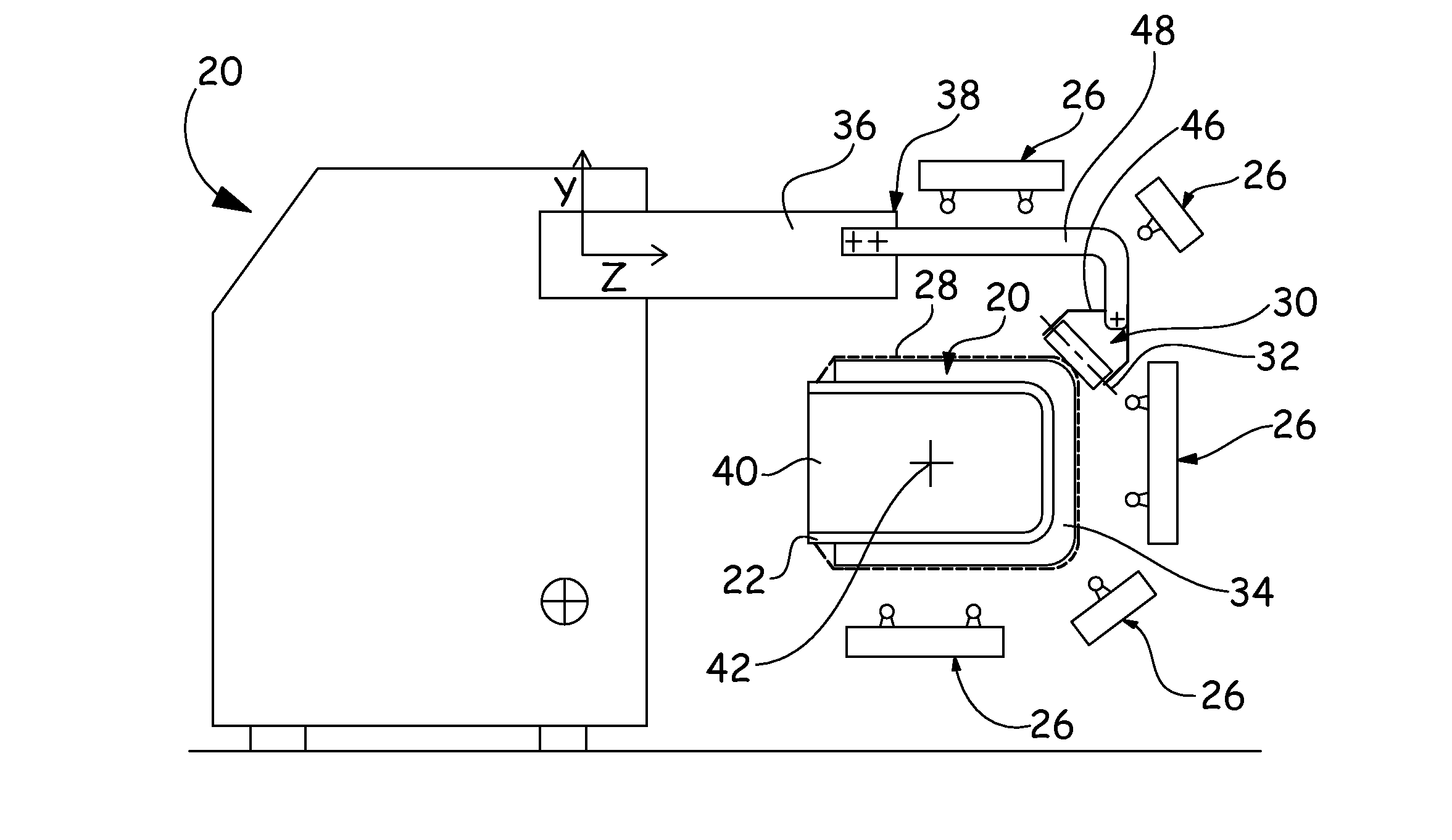
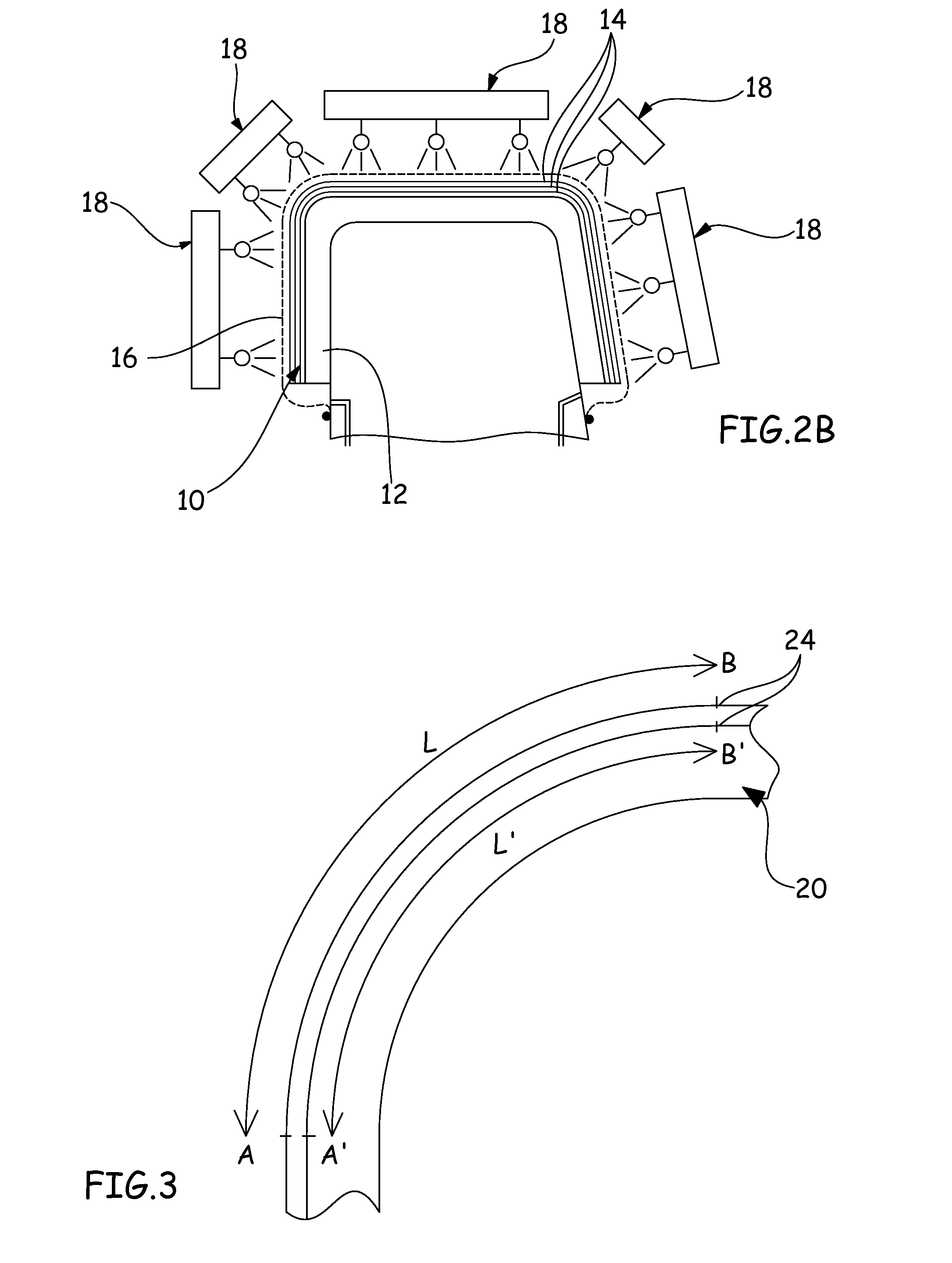
[0025]FIGS. 4A to 4C illustrate a device 22 of convex shape to which are connected pre-impregnated fiber layers 24, on one another, so as to produce a part 20 made of composite material after polymerization.

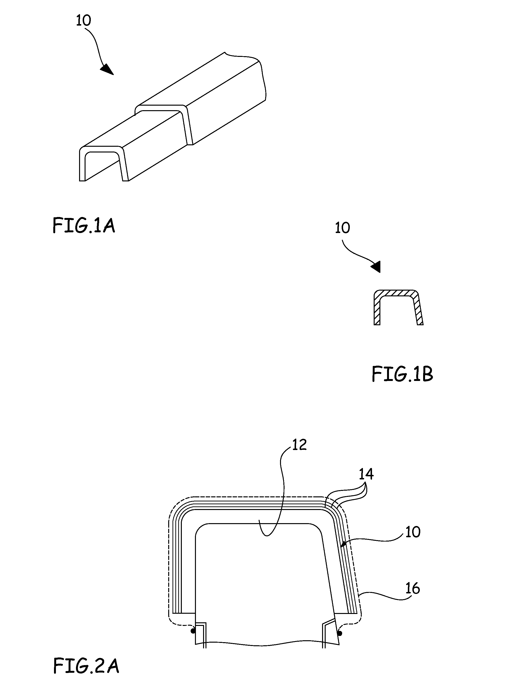
[0026]According to the illustrated example, the part 20 has a U-shaped profile along a transverse cutaway. Of course, the invention is not limited to this profile and can be applied to other parts with a profile that has at least one reduced radius of curvature. Reduced radius of curvature is defined as a radius at which the fibers can roll during the polymerization because of the contraction if the fiber layers 24 are not compacted during the deposition operation of said layers 24.

[0027]The device 22 is not described in more detail because it varies depending on the part that is to be produced. In addition, it is known to one skilled in the art and can be identical to devices 12 of the prior art.

[0028]According to the applications, the number of fiber layers, the nature of the f...


PUM

PropertyMeasurementUnit
Radiusaaaaaaaaaa

Abstract

A process for the production of a part made of composite material including at least one radius of curvature, includes a stage for deposition of pre-impregnated fiber layers (24) on a device (22) of convex shape on one another and for compacting the layers, characterized in that localized and repeated forces are applied in such a way as to cover the zone of the radius of curvature, at a given instant the forces being applied on a zone that is less than half of the zone of the radius of curvature, so as to compact the fiber layers (24) locally during the deposition stage.

Description

BACKGROUND OF THE INVENTION[0001]1. Field of the Invention[0002]This invention relates to a process for manufacturing a part made of composite material that comprises at least one radius of curvature, such as, for example, an angle bar or a stiffener with a U-shaped cross-section.[0003]2. Description of the Related Art[0004]FIGS. 1A and 1B show a stiffener 10 with a U-shaped cross-section. As illustrated in FIGS. 2A and 2B, this stiffener 10 can be produced by stacking pre-impregnated resin fiber layers 14 on a device 12 of convex shape.[0005]The fiber layers 14 can be deposited using a draping machine, according to the predetermined fiber orientations.[0006]After the deposition of the fiber layers, the unit, also covered by a bladder, is introduced into an autoclave and subjected to a cycle of temperature and pressure in such a way as to bring about the polymerization of the stiffener 10. During this polymerization stage, the pressure outside of the bladder can reach on the order o...

Claims


Application Information

Patent Timeline
IPC IPC(8): B29C65/70B29C70/02B29C70/34B29C70/38B29C70/54B29K105/08B29L31/00
CPCB29C70/342B29C70/34B29C70/386B29K2105/0872B29L2031/001B29C70/543B29D99/0003Y10T156/10B29C70/549B29C70/541
Inventor DE MATTIA, DENISBOYELDIEU, AURELIEN
Owner AIRBUS OPERATIONS (SAS)
Why Eureka
Try Eureka