Rotary combustion engine and hydraulic motor

a technology of hydraulic motor and divider member, which is applied in the direction of combination engines, rotary piston engines, rotary or oscillating piston engines, etc., can solve the problems of constant eccentric rings and distance between the sealing surface the inner surface of the driving, so as to improve the sealing effect and enhance the sealing contact of the divider member

Inactive Publication Date: 2015-06-16
GREITTEK
View PDF36 Cites 1 Cited by
  • Summary
  • Abstract
  • Description
  • Claims
  • Application Information

AI Technical Summary

Benefits of technology

[0007]The invention is thus based on control or a control component which implements the eccentricity path of the divider members and which is most preferably implemented separately and wherein the eccentricity path may easily be provided such that the distance between the opposite matching surfaces of the divider members can always be kept constant by an appropriate shape of the guide groove, which is typically slightly different from a circular orbit, e.g. slightly elliptical. As distinct from the previous, this component implementing the eccentric control now rotates along with the power shaft, which also enhances the sealing contact of the divider members with the inner surface of the eccentric ring. Instead, the basic operation of the device, i.e. the non-rotatoriness of the driving eccentric ring, remains exactly as before.
[0008]The solution according to the invention enables the previously problematic vibrations of the divider members and the resulting abnormal wear of the divider members and their matching surfaces to be eliminated. Now the running clearances of the divider members may easily be arranged appropriately and the operation of the seals provided at the ends of the divider members can be managed and thus the sealing effect be improved.
[0009]An additional advantage is that no inner eccentric ring that was previously used is necessary since, after all, its purpose was previously only to implement the control in question, in addition to the bearing system of the eccentric ring arrangement. It is now possible to mount the driving outer and only eccentric ring in bearings directly on the eccentric part of the power shaft.

Problems solved by technology

A problem with the solutions described in these patents is that the distance between the sealing surface of the divider members and the inner surface of the driving, i.e. the first, eccentric ring does not remain constant, owing to the paths of the system.

Method used


Image

  • Rotary combustion engine and hydraulic motor
  • Rotary combustion engine and hydraulic motor
  • Rotary combustion engine and hydraulic motor

Examples


Embodiment Construction

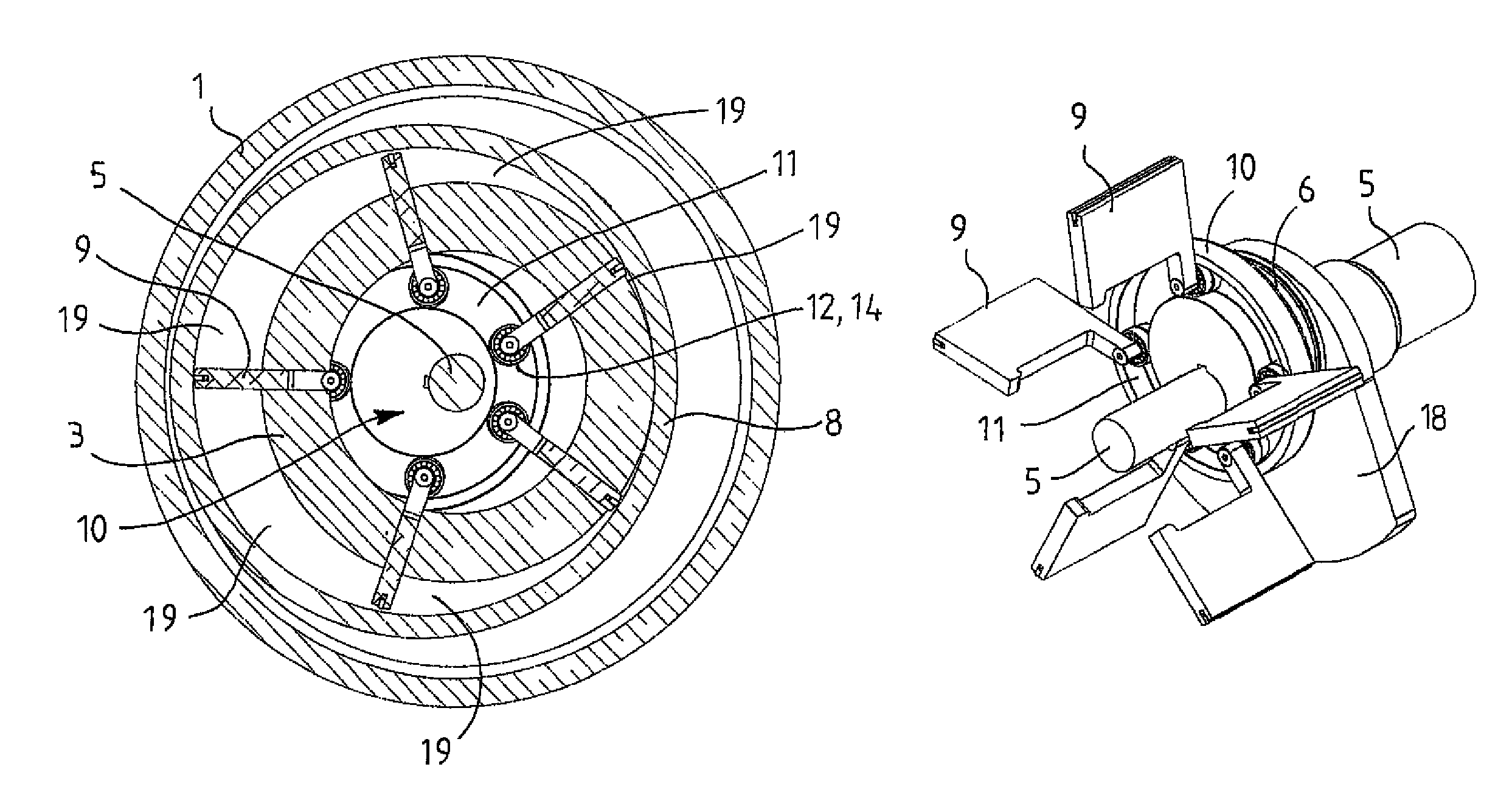
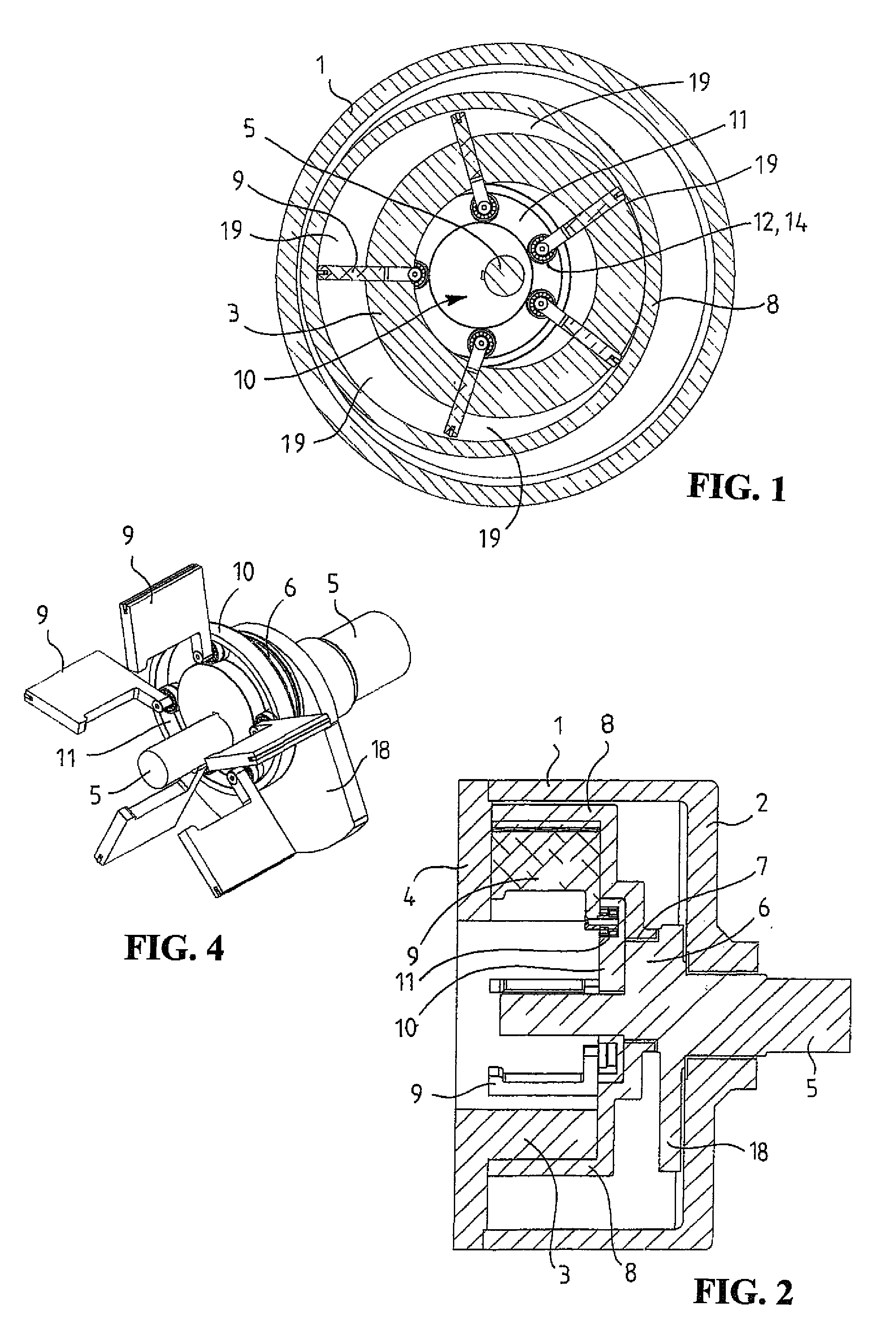
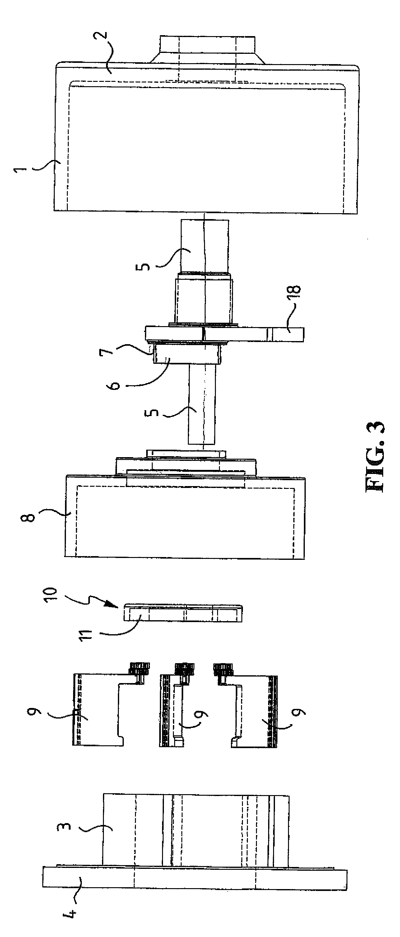
[0018]Referring first to FIGS. 1 to 3 in particular, a rotary engine shown therein comprises a non-rotary cylindrical outer casing 1 which is closed at its one end by a first end part 2, and a non-rotary inner casing 3 which, via a second end plate 4 provided at its one end, is fastened to one end edge of the outer casing 1. These components 1 to 4 mainly constitute the outer parts of the engine.

[0019]The components 1 to 4 encompass, first, a power shaft 5 arranged inside the inner casing 3 and mounted in bearings with respect to its centre line A coaxially with respect to the inner casing 3 to the end plates 2 and 4. The power shaft 5 is provided with an eccentric part 6, which is essential for the operation of the engine, and a bearing 7 is mounted on the surface thereof. A driving eccentric ring 8, which is also essential for the operation of the engine, is placed between the outer casing 1 and the inner casing 3, and it is mounted by the aforementioned bearing 7 on an eccentric ...


PUM


Abstract

A rotary engine and a hydraulic motor including non-rotary outer and inner casings; a power shaft with an eccentric part; a driving eccentric ring between the outer and inner casings and mounted on the eccentric part; a combustion or pressure chamber between the eccentric ring and the inner casing such that the eccentric ring drives the power shaft by substantially non-rotating eccentric movement; dividers for dividing the combustion chamber into at least two parts, the dividers extend through the inner casing and are in contact with an inner surface of the driving eccentric ring; and an eccentric device (or control) for driving the dividers back and forth with respect to the inner casing. The eccentricity of the eccentric device corresponds with the eccentricity of the eccentric part of the power shaft. The eccentric device has a guide groove which implements an eccentric path and to which the dividers are connected.

Description

BACKGROUND OF THE INVENTION[0001]The invention relates to a rotary combustion engine comprising a non-rotary outer casing; a non-rotary inner casing; a power shaft provided with an eccentric part; a driving eccentric ring provided between the outer casing and the inner casing and mounted in bearings on the eccentric part of the power shaft; a combustion chamber arrangement for burning a mixture of fuel and air supplied into the engine between the eccentric ring and the inner casing such that the eccentric ring drives the power shaft by means of substantially non-rotating eccentric movement; divider members for dividing the combustion chamber arrangement into at least two parts of equal size, whereby the divider members extend through the inner casing and are in close contact with an inner surface of the driving eccentric ring; an eccentric device or control for driving the divider members back and forth with respect to the inner casing, whereby the eccentricity of the eccentric devi...

Claims


Application Information

Patent Timeline
Patent Type & Authority Patents(United States)
IPC IPC(8): F02B53/04F01C1/344F01C1/348F01C21/08F03C2/30F02B53/00
CPCF01C1/3442F01C1/348F01C21/0836F03C2/304F01C1/344F04C2/344
Inventor VIITAMAKI, TAPIOVIITAMAKI, MARKUS
Owner GREITTEK
Why Eureka
Try Eureka