Seal ring on cover plate component, cover plate component, upper cover component and electric appliance

A sealing ring and cover assembly technology, which is applied in the directions of cooking utensil lids, household appliances, frying pans, etc., can solve problems such as affecting customer experience, condensation of condensed water, slipping on the outer cover of the rice cooker, etc., to achieve good customer experience. Good sealing effect and compact electrical structure

Active Publication Date: 2018-03-06
FOSHAN SHUNDE MIDEA ELECTRICAL HEATING APPLIANCES MFG CO LTD
View PDF12 Cites 0 Cited by
  • Summary
  • Abstract
  • Description
  • Claims
  • Application Information

AI Technical Summary

Problems solved by technology

[0002] like figure 1 and figure 2 As shown, in the current electric pressure cooker, electric rice cooker and other products, the sealing ring 2 is installed on the inner surface of the cover plate assembly 1. When the cover plate assembly 1 is fastened on the cooking vessel 3, due to the structural design of the sealing ring 2 , the c

Method used


Image

  • Seal ring on cover plate component, cover plate component, upper cover component and electric appliance
  • Seal ring on cover plate component, cover plate component, upper cover component and electric appliance
  • Seal ring on cover plate component, cover plate component, upper cover component and electric appliance

Examples


Embodiment 1

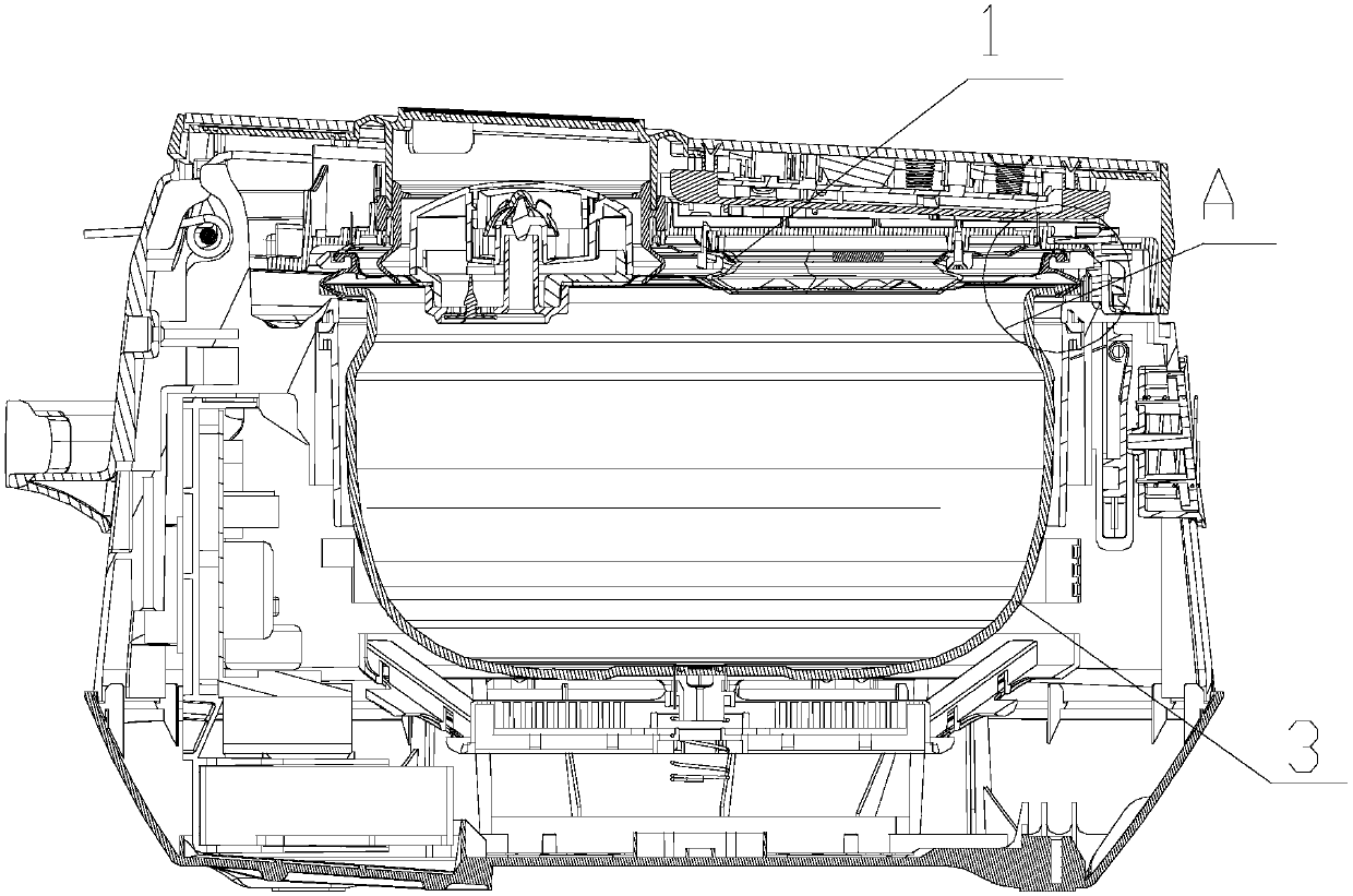
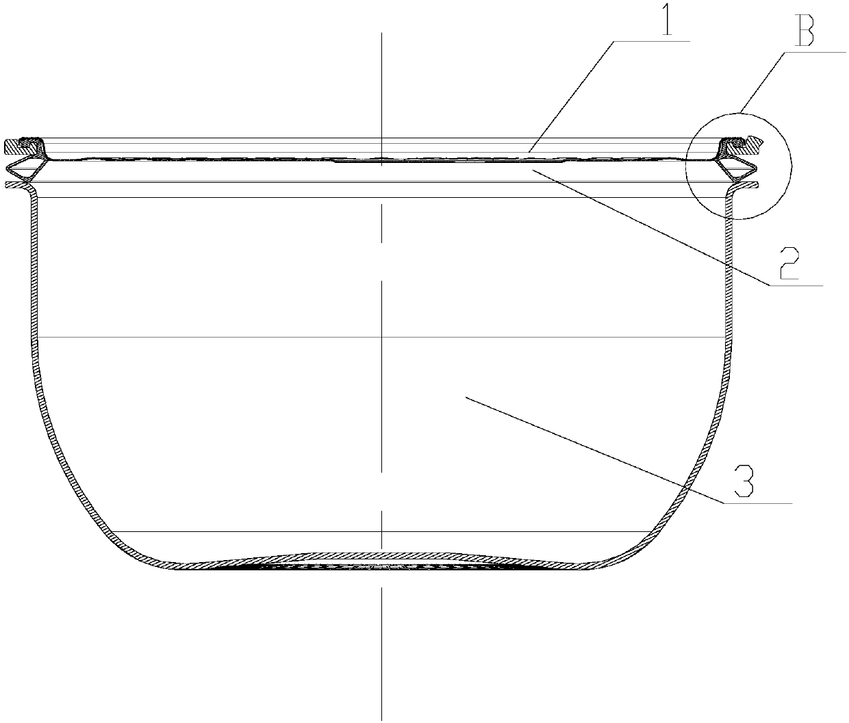
[0040] Such as Figure 3 ~ Figure 6As shown, the sealing ring on a cover plate assembly of this embodiment includes an integrally connected installation part 21 and a sealing part 22. On one side of the assembly 1 , the sealing portion 22 extends from one side of the cover assembly 1 in a direction away from the cover assembly; when the cover assembly 1 is fastened on the cooking vessel 3 , The sealing part 22 abuts on the open edge 31 of the cooking vessel 3 and one side of the sealing part 2 inside the cooking vessel 3 is a water diversion slope 225 , and the water diversion slope 225 is away from the end of the cover plate assembly 1 It is located directly below or outside the end close to the cover plate assembly 1, that is, the vertical distance between the end of the water diversion slope 225 away from the cover plate assembly 1 and the central axis of the sealing ring 2 is greater than or equal to that of the water diversion slope 225 close to The vertical distance bet...

Embodiment 2

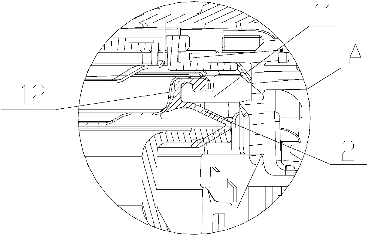
[0054] This embodiment provides a cover assembly, such as image 3 and Figure 4 As shown, the cover plate assembly 1 includes a cover plate body 12, a ring-shaped pressure plate 11 and a sealing ring 2 as described in Embodiment 1, and the pressure plate 11 is crimped on the peripheral edge of the cover plate body 12 And an annular gap 13 is formed between the cover plate body 12, the mounting part 21 is sealed and crimped in the annular gap 13 and is located on the inner ring side of the pressure plate 11, and the longitudinal section is "Γ" shaped The mounting part 21 is crimped in the annular gap 13, so that the clamping between the mounting part 21 and the pressure plate 11 is firmer; the sealing part 22 extends from the annular gap 13 in a direction away from the cover plate assembly 1 and the annular The gap 13 is sealed and covered. The cover plate assembly of this embodiment is configured by setting that when the sealing ring abuts on the open edge of the cooking ve...

Embodiment 3

[0056] This embodiment provides an upper cover assembly, including a cover body and the cover assembly 1 as described in Embodiment 2, and the other side of the cover assembly 1 is connected to the cover body. The upper cover assembly of this embodiment has a good sealing effect, which facilitates the condensed water to slide out from the sealing ring, keeps the sealing ring in an anhydrous state, and avoids water accumulation inside the sealing ring due to steam condensation during the cooking process.


PUM

PropertyMeasurementUnit
Hardnessaaaaaaaaaa

Abstract

The invention relates to a seal ring on a cover plate component, the cover plate component, an upper cover component and an electric appliance. The seal ring comprises a mounting portion and a sealingportion which are integrally connected; the vertical section of the mounting portion is represented into an inverted L-shaped form and the mounting portion is arranged on one side face of the cover plate component in a sealed mode; the sealing portion extends from one side face of the cover plate component along a direction back away from the cover plate component; the sealing portion abuts against an opening edge of a cookware and the side face, which is located within the cookware, of the sealing portion is a water diversion inclined plane when the cover plate component is buckled on the cookware; and the end, away from the cover plate component, of the water diversion inclined plane is located below or at the outer side of the end, close to the cover plate component, of the water diversion inclined plane. According to the seal ring provided by the invention, by arranging the water diversion inclined plane, condensed water can slide down from the seal ring in one hand, so that the seal ring can be kept under a water-free state, and a phenomenon of water accumulation in the seal ring due to vapor condensation in a cooking process can be prevented; and in the other hand, soup or rice grains, which splash on the water diversion inclined plane, can be conveniently cleaned.

Description

technical field [0001] The invention relates to the technical field of small household appliances, in particular to a sealing ring on a cover assembly, a cover assembly, an upper cover assembly and an electrical appliance. Background technique [0002] Such as figure 1 and figure 2 As shown, in the current electric pressure cooker, electric rice cooker and other products, the sealing ring 2 is installed on the inner surface of the cover plate assembly 1. When the cover plate assembly 1 is fastened on the cooking vessel 3, due to the structural design of the sealing ring 2 , the condensed water generated during the cooking process or the condensation process is easy to condense in the sealing ring 2, and the condensed water slides into the outer cover of the rice cooker after the user opens the cover, which affects the customer's experience effect, and more seriously, it will be caused by water. The problem caused user complaints. Contents of the invention [0003] The ...

Claims


Application Information

Patent Timeline
IPC IPC(8): A47J27/08A47J36/06A47J37/10
CPCA47J27/08A47J36/06A47J37/101Y02B40/00
Inventor 梅若愚陈炜杰何柏锋潘典国刘小凯周亚
Owner FOSHAN SHUNDE MIDEA ELECTRICAL HEATING APPLIANCES MFG CO LTD
Why Eureka
Try Eureka