Adaptable multi-element vibration isolator

a multi-element, vibration isolation technology, applied in the direction of shock absorbers, mechanical devices, springs/dampers, etc., can solve the problems of insufficient natural frequency response of conventional isolation mounts, and achieve the effect of reducing space occupation, improving quality and performance, and facilitating inspection

Inactive Publication Date: 2015-06-16
THE UNITED STATES OF AMERICA AS REPRESENTED BY THE SECRETARY OF THE NAVY
View PDF16 Cites 4 Cited by
  • Summary
  • Abstract
  • Description
  • Claims
  • Application Information

AI Technical Summary

Benefits of technology

[0012]Typical inventive embodiments have replaceable elastomeric elements that can be varied, depending on the application requirements. Because of the present invention's flexibility in fabricating and implementing parts and components, quality and performance can be optimized. For instance, damping can be selectively varied, as required. Typical inventive practice provides snubber (restraint) capability within the envelope / footprint of the inventive assembly, the inventive mount thereby taking up less space; nevertheless, the present invention has the versatility to be practiced so that snubber capability is situated outside the envelope / footprint of the inventive assembly. A typical inventive configuration allows for ease of inspection of the elastomeric components. Inventive practice can be attributed with recyclability; for instance, the metallic housings can be reused when the elastomer needs replacement or exceeds its useful life.
[0013]Molding of the present invention's elastomeric bodies is typically facilitated by shaped metallic bodies that also represent fastening points for assembly of the inventive mount. The metallic components on the elastomer can be used as adapters as part of an injection molding process; in particular, the elastomer can be poured more effectively through use of the metallic components whereby the metallic components and the elastomeric component therebetween become molded as one. The present invention's multiple conical elements are relatively small, and hence their fabrication is easier than fabrication for larger mount applications. Better control during manufacture of smaller molds, as compared with control during manufacture of larger (e.g., single-made) molds such as for larger weight-capacity mounts, implies a more consistent product and superior performance characteristics.

Problems solved by technology

However, generally speaking, conventional isolation mounts have not been entirely satisfactory, in terms of their natural frequency response, for purposes of either controlling unwanted vibrations or reducing acoustic energy propagation.

Method used


Image

  • Adaptable multi-element vibration isolator
  • Adaptable multi-element vibration isolator
  • Adaptable multi-element vibration isolator

Examples


Embodiment Construction

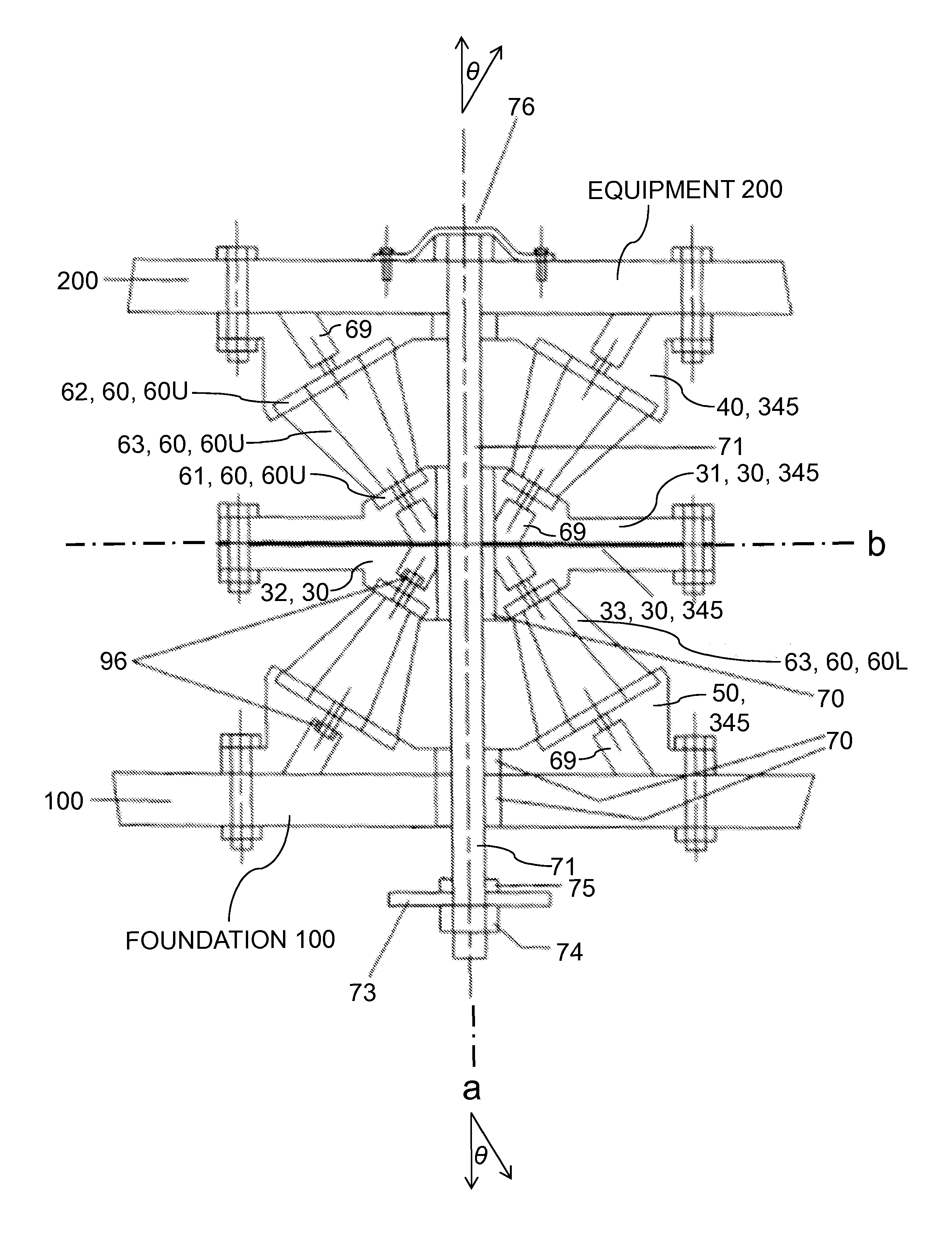
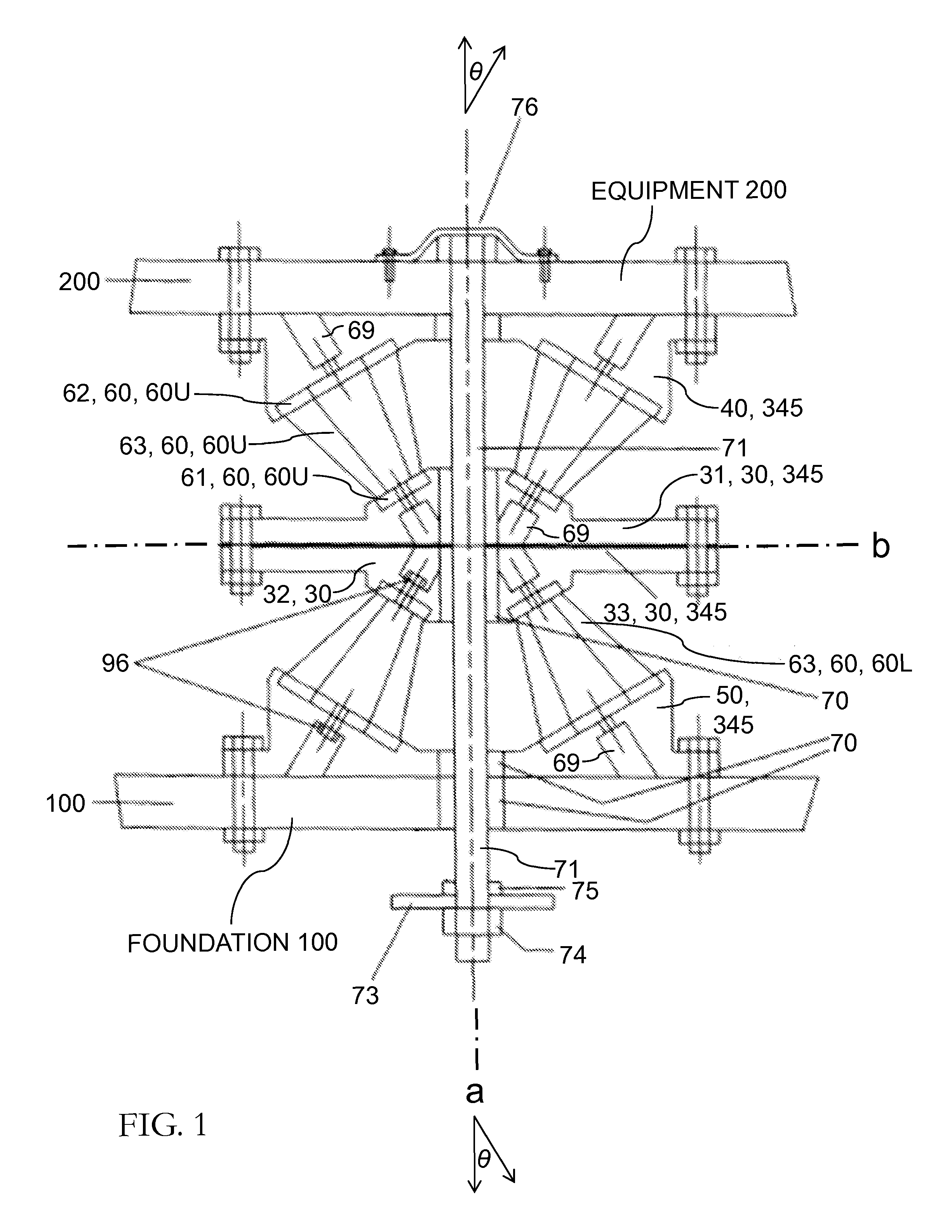
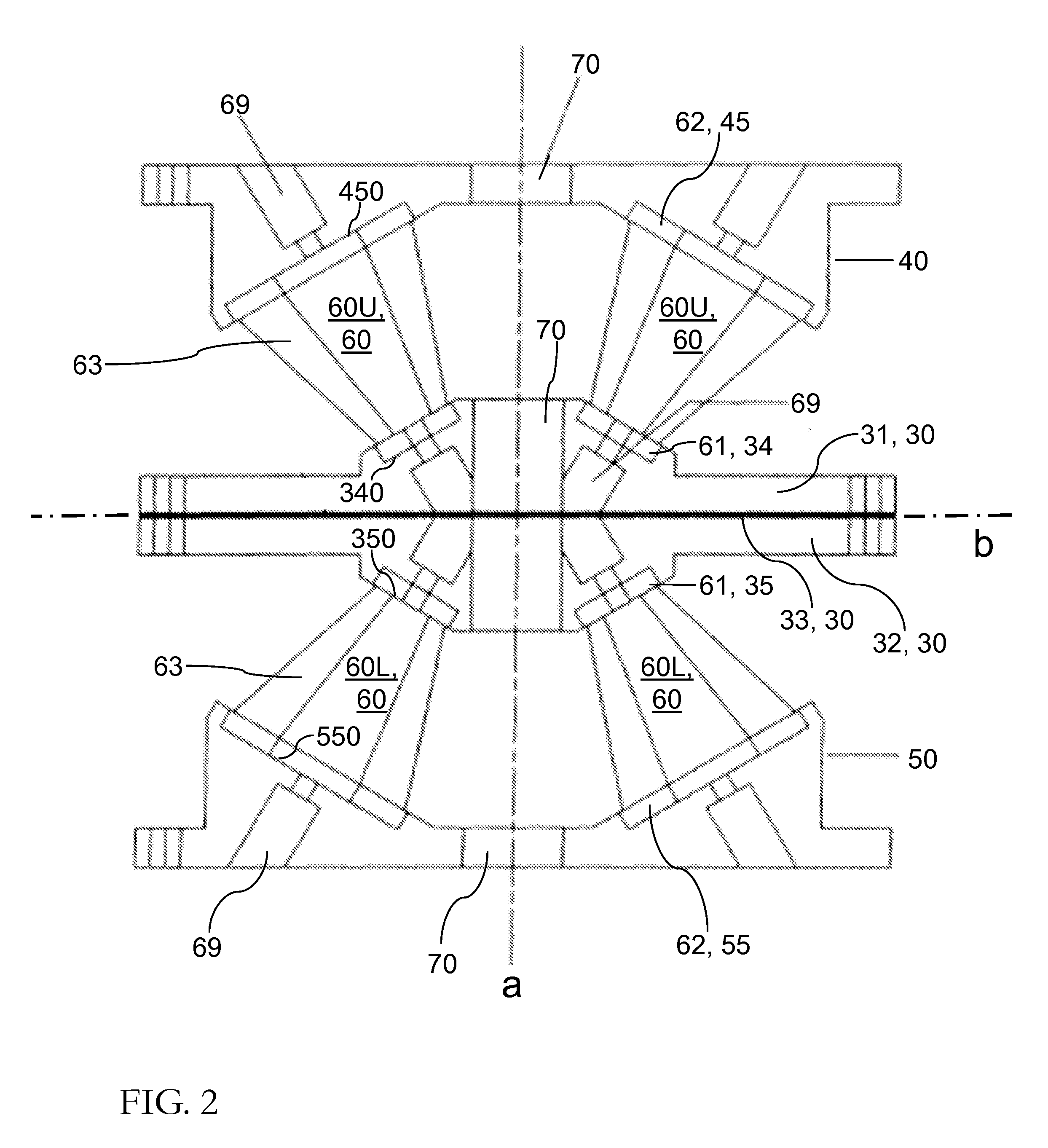
[0034]Referring to the figures and particularly to FIG. 1 and FIG. 2, the present invention's vibration / shock isolation mount is characterized by a vertical geometric axis of symmetry a, and by a horizontal geometric bisector plane b. Geometric axis a is perpendicular to geometric plane b. The inventive mount depicted in FIGS. 1 and 2 includes eight resilient elements 60 and a housing 345 for the resilient elements 60. The eight elements 60 that are shown are identical, or practically so. The housing 345 has three main rigid (e.g., metal / metallic) sections, delimited according to situation along axis a, viz., a middle section 30, an upper end section 40, and a lower end section 50.

[0035]Four of the resilient elements 60 are “upper” resilient elements 60U; four of the resilient elements 60 are “lower” resilient elements 60L. Upper resilient elements 60U are vertically collocated (at least approximately so) with respect to lower resilient elements 60L. Housing 345 holds upper resilien...


PUM


Abstract

The present invention's vibration/shock amelioration device, as typically embodied, has a geometric device axis and includes two axial endplates, an intermediate support structure, and at least six truncated-conical resilient (e.g., elastomeric) elements. The intermediate support structure is equidistant between the endplates and lies in a geometric bisector plane that is perpendicular to the device axis. Each resilient element has a geometric conical axis, a larger-diameter axial end, and a smaller-diameter axial end. The resilient elements are fixed between the support structure and an endplate and are arranged symmetrically with respect to the device axis whereby the conical axes intersect the device axis at oblique angles and the smaller-diameter axial ends are closer to the bisector plane than are the larger-diameter axial ends. The intermediate support structure can include a single rigid piece, or a composite unit having a pair of rigid members and a resilient (e.g., elastomeric) member sandwiched therebetween.

Description

BACKGROUND OF THE INVENTION[0001]The present invention relates to isolation of vibration and / or shock, more particularly to passive isolation implementing resilient (e.g., elastomeric) material.[0002]In military and commercial contexts, various methods and devices have been known for effecting passive vibration isolation and / or passive shock isolation. Such methods and devices are commonly practiced in association with low natural frequency hardware (e.g., machinery) in order to isolate vibrations at relatively low natural frequencies. Vibration isolation mounts have been developed that seek to address low frequency requirements for vibration and / or shock. However, generally speaking, conventional isolation mounts have not been entirely satisfactory, in terms of their natural frequency response, for purposes of either controlling unwanted vibrations or reducing acoustic energy propagation.[0003]Among the practical considerations for vibration / shock mounts is the desirability of redu...

Claims


Application Information

Patent Timeline
Patent Type & Authority Patents(United States)
IPC IPC(8): F16F7/00F16F1/40F16F3/08
CPCF16F1/40F16F1/406F16F3/08F16F1/373F16F3/0876
Inventor PLANGETIS, GUS F.
Owner THE UNITED STATES OF AMERICA AS REPRESENTED BY THE SECRETARY OF THE NAVY
Why Eureka
Try Eureka