Electrical assembly for connecting components of a lighting system for illuminating store shelving

a technology for lighting systems and components, applied in the direction of lighting and heating apparatus, coupling device connections, lighting support devices, etc., can solve the problems of inconvenient assembly, poor lighting and shelving units, and substantial skill and effort required to assemble and disassemble such prior art lighting systems. , to achieve the effect of quick connection and preventing damage to the track

Inactive Publication Date: 2015-06-16
STREATER
View PDF23 Cites 18 Cited by
  • Summary
  • Abstract
  • Description
  • Claims
  • Application Information

AI Technical Summary

Benefits of technology

[0011]The connectors associated with the wiring harnesses are designed to ensure proper polarity of the wiring is maintained (i.e., the negative terminals are connected to the negative side of the circuit and the positive terminals are connected to the positive side of the circuit). Also, the connectors are all designed so they are quickly connected and held in place for use. However, when shelving is disassembled or individual shelves are moved, the wiring harness automatically disconnects from either the track or the electrical device (e.g., a power supply or light fixture) to prevent damage to the track, the wiring harness, and the electrical device.

Problems solved by technology

Further, such lighting and shelving units are bland and do not serve to “catch the eye” of the retail customer and do little to attract a customer to a particular item of merchandise.
Various lighting systems for shelving units have been employed to overcome these deficiencies, but they are often costly, laborious to assemble, and involve numerous electrical connections which must be made after the shelving unit is completely assembled.
Substantial skill and effort is required to assemble and disassemble such prior art lighting systems.
If sufficient care is not exercised, such prior art lighting systems increase the risk of electrical shock or even fire.
One undesirable aspect of many such lighting systems is that, after installation, dangling wires detract from achieving the desired effect.

Method used


Image

  • Electrical assembly for connecting components of a lighting system for illuminating store shelving
  • Electrical assembly for connecting components of a lighting system for illuminating store shelving
  • Electrical assembly for connecting components of a lighting system for illuminating store shelving

Examples


Embodiment Construction

[0036]This description of the preferred embodiment is intended to be read in connection with the accompanying drawings, which are to be considered part of the entire written description of this invention. In the description, relative terms such as “lower”, “upper”, “horizontal”, “vertical”, “above”, “below”, “up”, “down”, “top” and “bottom”, as well as derivative thereof (e.g., “horizontally”, “downwardly”, “upwardly”, etc.) should be construed to refer to the orientation as then described or as shown in the drawings under discussion. These relative terms are for convenience of description and do not require that the apparatus be constructed or operated in a particular orientation. Terms such as “connected”, “connecting”, “attached”, “attaching”, “joined”, and “joining” are used interchangeably and refer to one structure or surface being secured to another structure or surface or integrally fabricated in one piece unless expressly described otherwise.

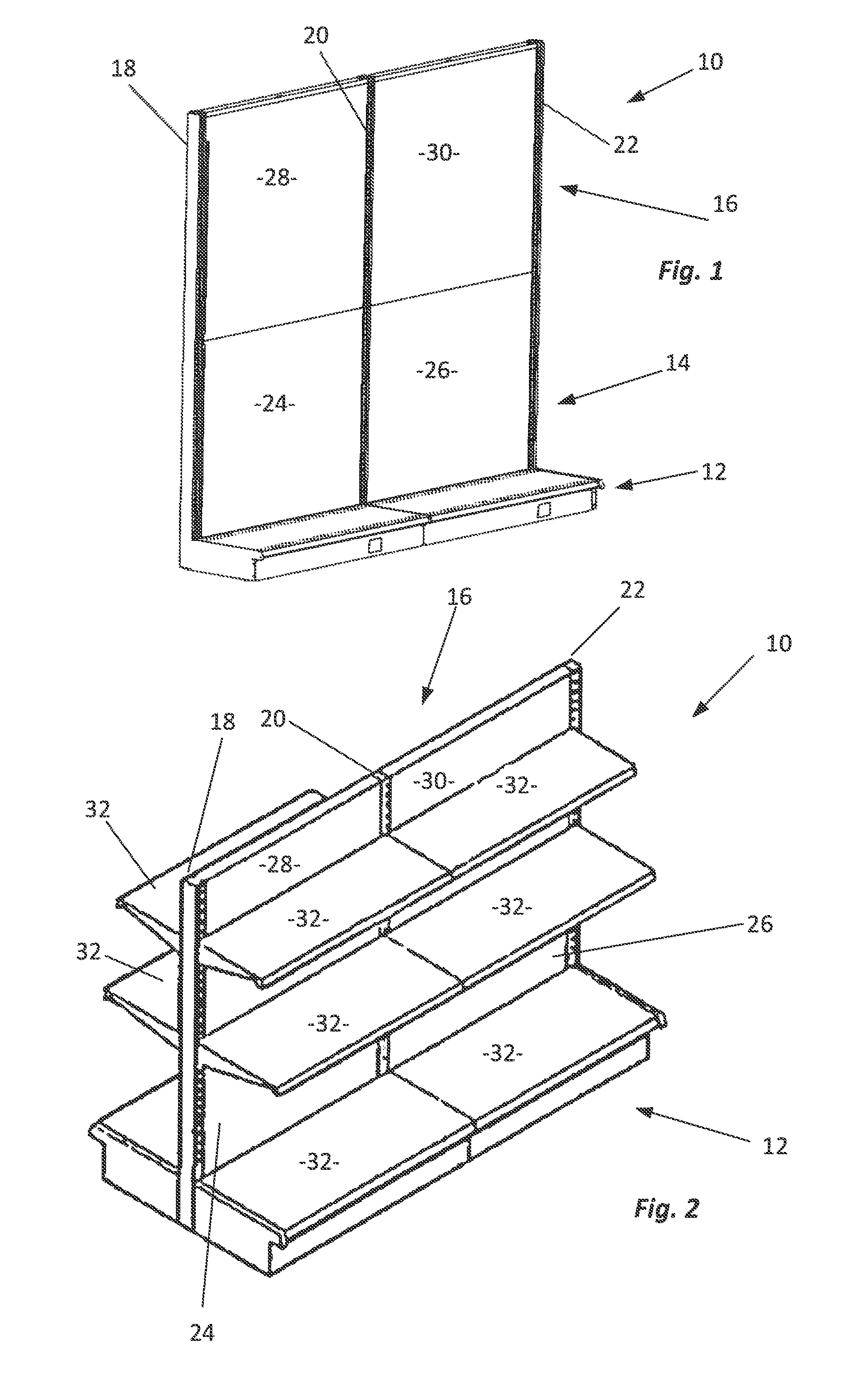
[0037]FIGS. 1 and 2 illustrate g...


PUM


Abstract

Quick-connect disconnect connectors are provided as part of an electrical assembly used to electrically couple components to the end of an electrical track section. The connectors have a tongue portion insertable into the end of the track only one way to ensure against cross-wiring and include structures for retaining electrical contacts and strain reliefs. The connectors readily disconnect from the end of the track when force is applied which might be sufficient to damage the track or electrical assembly to prevent such damage.

Description

CROSS-REFERENCED TO RELATED APPLICATIONS[0001]Not applicableSTATEMENT REGARDING FEDERALLY SPONSORED RESEARCH OR DEVELOPMENT[0002]Not applicableBACKGROUND OF THE INVENTION[0003]I. Field of the Invention[0004]The present invention relates generally to lighting systems for display cases and shelving units used by merchants. More specifically, the present invention relates to quick-connect and disconnect connectors forming a part of such lighting systems which ensure that no cross-wiring occurs during the assembly process.[0005]II. Related Art[0006]Various forms of lighting have been employed in retail establishments. Lighting is used on signage, to provide security, to accent and better display product features, to enhance the prominence and attractiveness of merchandise, and to affect the mood of customers. The eye is drawn to brighter areas of contrasting light. Reading of packaging and labeling is easier in well lighted areas.[0007]Many retail establishments employ overhead ambient ...

Claims


Application Information

Patent Timeline
Patent Type & Authority Patents(United States)
IPC IPC(8): H01R25/00F21V21/34H01R13/58H01R25/14
CPCF21V21/34H01R13/582H01R25/14H01R13/5825H01R25/145A47B2220/0075A47B2097/003
Inventor LINDBLOM, THOMAS G.JENSEN, WAYNE LEE
Owner STREATER
Why Eureka
Try Eureka