In-situ overheat alert for equipment

a technology for equipment and overheating, applied in the field of equipment, can solve problems such as substantial heat generation within a particular, heavily loaded, manufacturing uni

Inactive Publication Date: 2015-06-16
GM GLOBAL TECH OPERATIONS LLC
View PDF27 Cites 3 Cited by
  • Summary
  • Abstract
  • Description
  • Claims
  • Application Information

AI Technical Summary

Problems solved by technology

Often the equipment is used in circumstances that make maximum use of its design capabilities and may result in substantial heat generation within a particular heavily loaded, manufacturing unit.

Method used


Image

  • In-situ overheat alert for equipment
  • In-situ overheat alert for equipment
  • In-situ overheat alert for equipment

Examples


Embodiment Construction

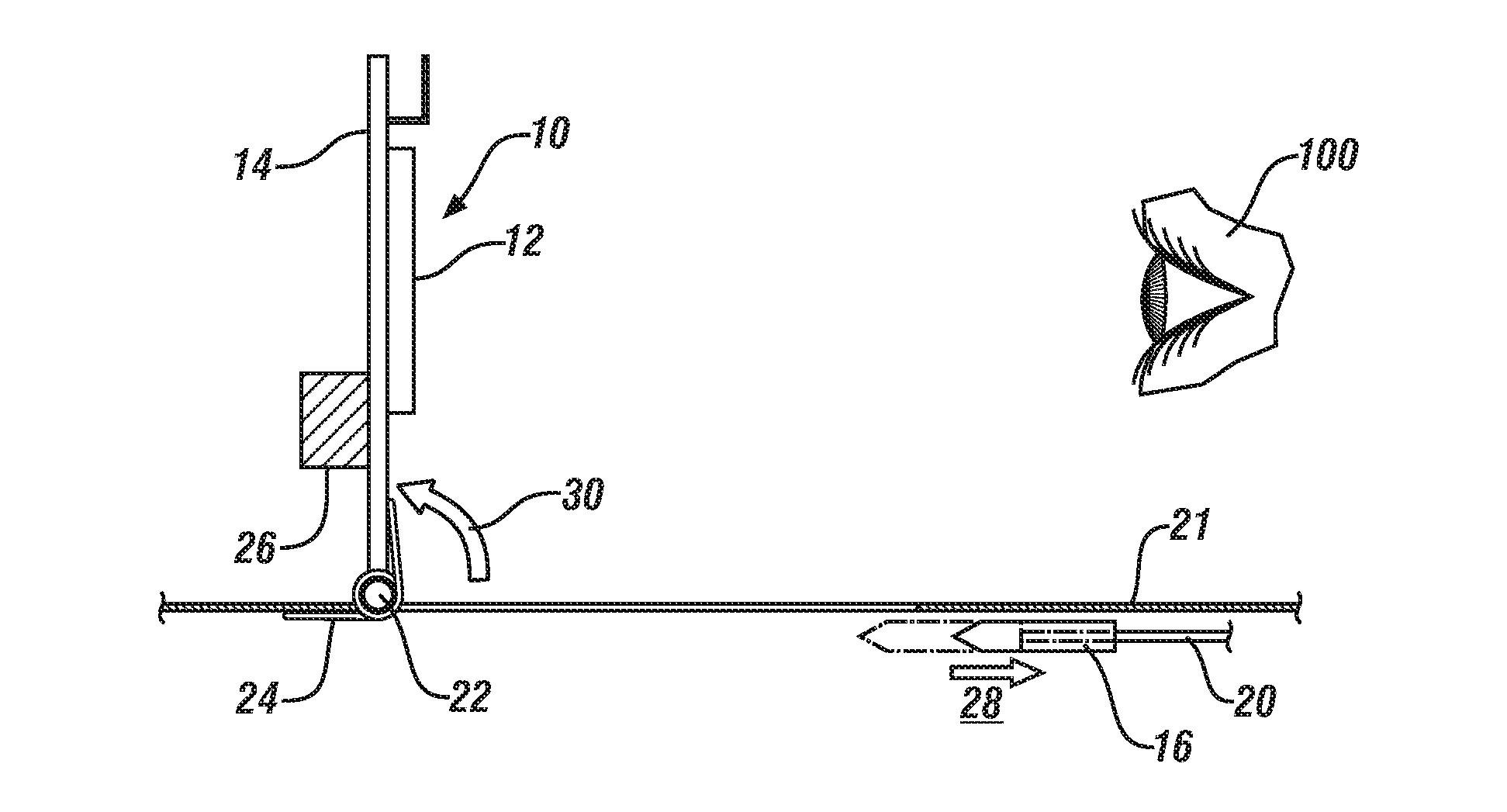
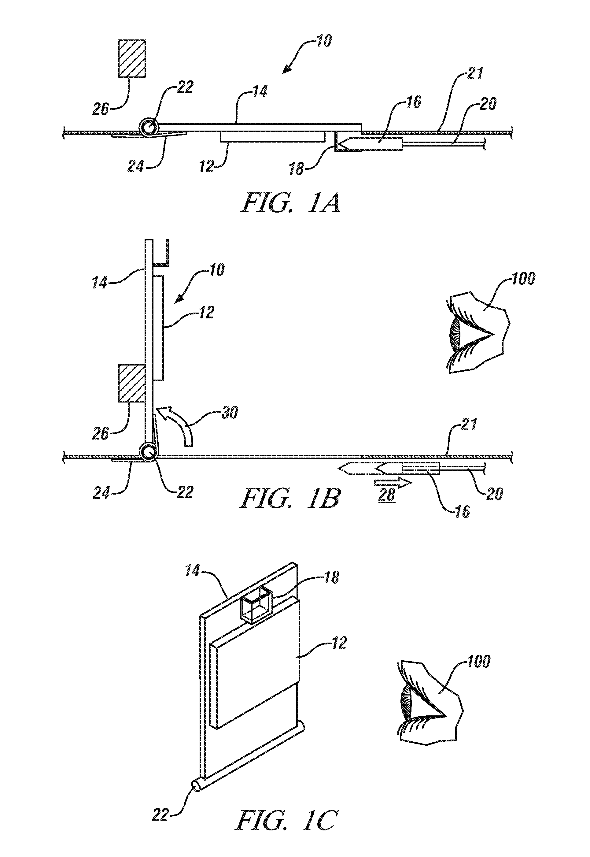
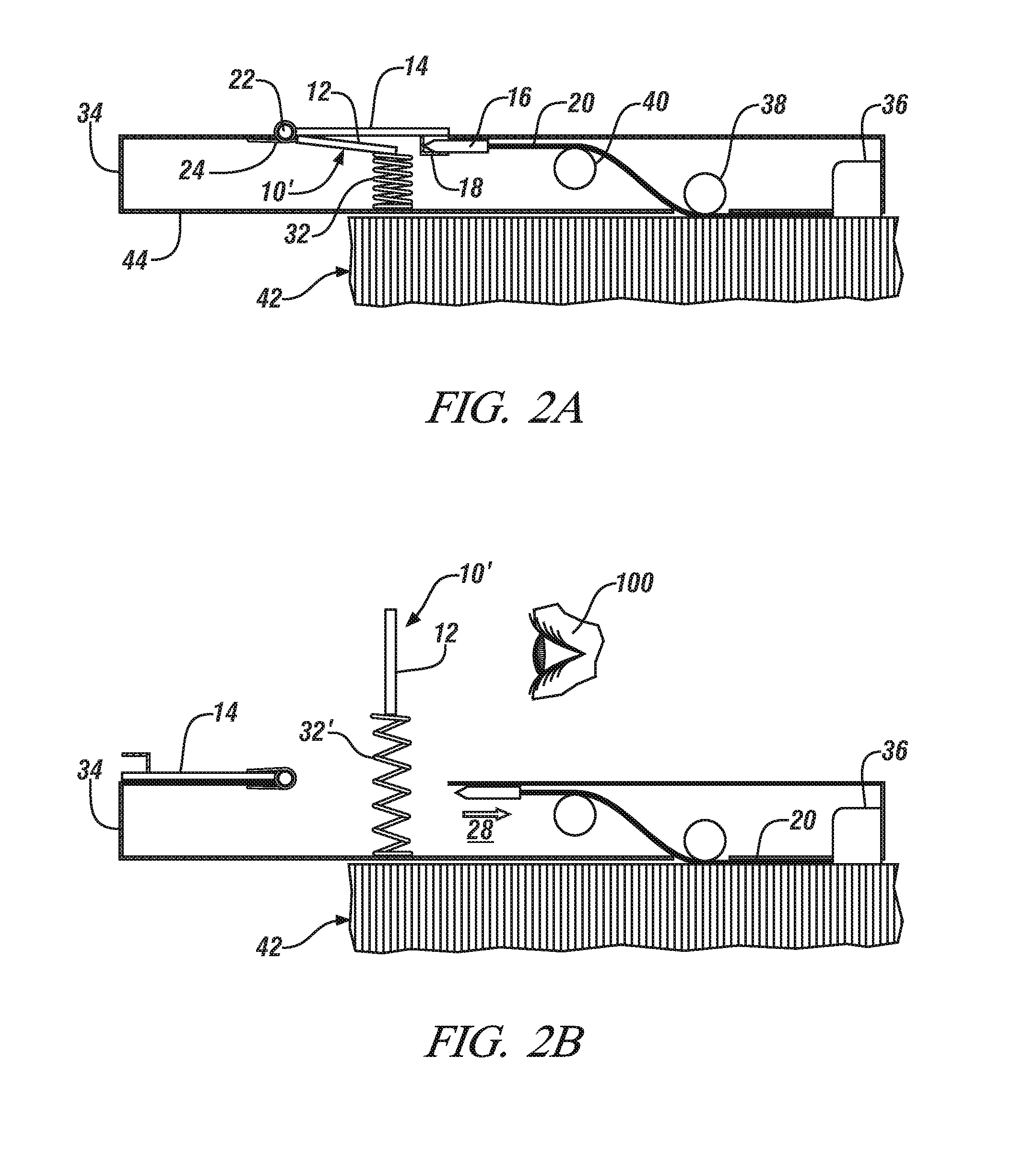
[0016]The subject invention provides in-situ overheat detecting devices to protect operating machines and equipment. The devices are shaped to be placed on a surface of the machine which would experience a temperature increase when the machine experiences overheating. The overheat detecting devices use temperature-sensitive, active material actuators which experience a change in shape or volume when heated by contact with a machine surface to a pre-determined temperature range. Upon undergoing such a shape or volume change, the overheat detecting devices release, or render visible, a ‘flag’ or similar visual member to alert an operator or passer-by to an over-temperature event. Such a flag or visual indicator may be generally planar and of suitable shape and size, with surface coloration or other indicia to readily call attention to itself. Typically the flag member may be generally rectangular in form and at least one inch in minimum dimension and up to about four inches in maximum...


PUM

PropertyMeasurementUnit
temperatureaaaaaaaaaa

Abstract

Malfunction or failure of mechanical, electrical and electro-mechanical equipment, for example equipment used in manufacturing operations, is often preceded by an increase in the operating temperature of at least some portion of the equipment. A temperature-sensitive, active material-containing actuator is pre-selected to operate at a pre-determined temperature indicative of impending equipment failure and placed in thermal contact with the equipment. If the equipment achieves the pre-selected temperature the actuator signals this by displaying a flag or providing some other passive visual indication. Alternatively, or additionally, the actuator may issue an electrically-powered alert including visual or audible alerts or a wireless communication. Selected actuators are based on smart materials including shape memory alloys (SMA), shape memory polymers (SMP) and paraffin wax, all of which may be adapted to operate over a temperature range sufficient to encompass the expected range of pre-determined temperatures.

Description

TECHNICAL FIELD[0001]This disclosure pertains to devices adapted to fit on equipment, such as is used, for example, in manufacturing operations, each fitted-device serving to give notice of overheating of the machine to which it is attached or thermally connected. More specifically, this disclosure pertains to devices in which selected materials that are physically transformed at a predetermined machine-overheat temperature, respond to release a visible overheat flag or sign. The release of the visible overheat sign can be further used to initiate an audible warning signal, and can also initiate a signal for preserving a record of the overheating event.BACKGROUND OF THE INVENTION[0002]Modern manufacturing operations and other operating devices use many types of equipment that are subjected to loads that cause heating in portions of the particular machine or unit. Sometimes the heating occurs in electrically powered equipment, such as electric motors, welding transformers, and weldin...

Claims


Application Information

Patent Timeline
Patent Type & Authority Patents(United States)
IPC IPC(8): G01B5/02G01K5/56G01K5/54G01K1/02G08B21/18G08B5/02G08B17/02G08B17/04
CPCG08B5/02G01K1/02G08B21/187G08B17/02G08B17/04
Inventor JOHNSON, NANCY L.BROWNE, ALAN L.MENASSA, ROLAND J.
Owner GM GLOBAL TECH OPERATIONS LLC
Why Eureka
Try Eureka