Method of implanting an aortic stent

a technology of aortic stent and aortic valve, which is applied in the field of stents, can solve the problems of fatal complication, fatal myocardial infarction, and the way the main stent b>7/b> is disposed in the ascending aorta cannot be achieved by minimally invasive surgery

Inactive Publication Date: 2015-06-30
VICTOR ACTION LTD
View PDF3 Cites 5 Cited by
  • Summary
  • Abstract
  • Description
  • Claims
  • Application Information

AI Technical Summary

Problems solved by technology

Furthermore, the way the main stent 7 is disposed in the ascending aorta cannot be achieved by a minimally invasive surgery.
When there is a cut on the inner wall of the blood vessel, the blood stream with high pressure is pouring into the cut and tearing the tunica intima 6 out of other layers of arterial wall, which can be a fatal complication.
More seriously, the orifice of coronary artery that located at aortic rout would be obstruction by hematoma compression and leading fatal myocardial infarction.

Method used


Image

  • Method of implanting an aortic stent
  • Method of implanting an aortic stent
  • Method of implanting an aortic stent

Examples


Embodiment Construction

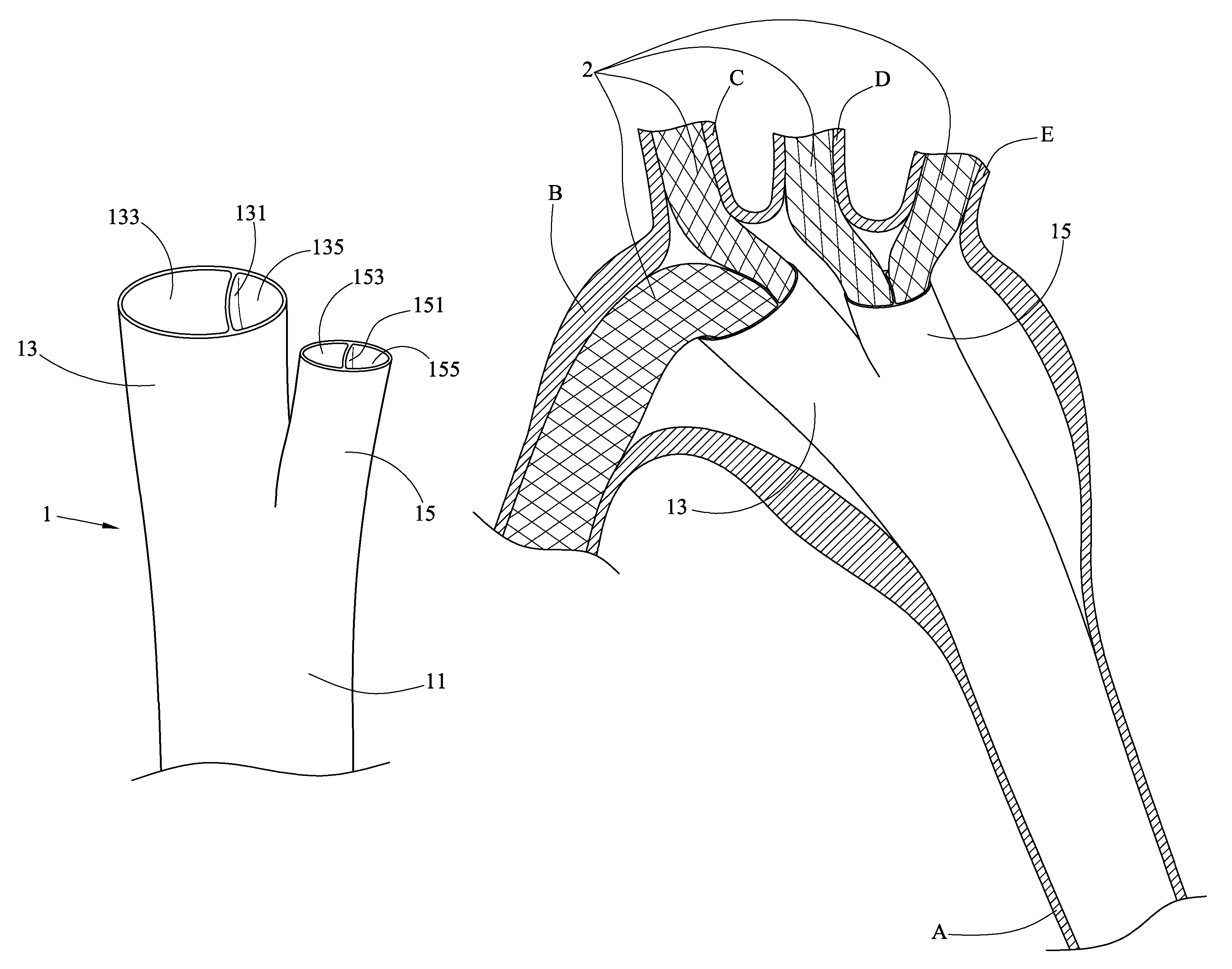
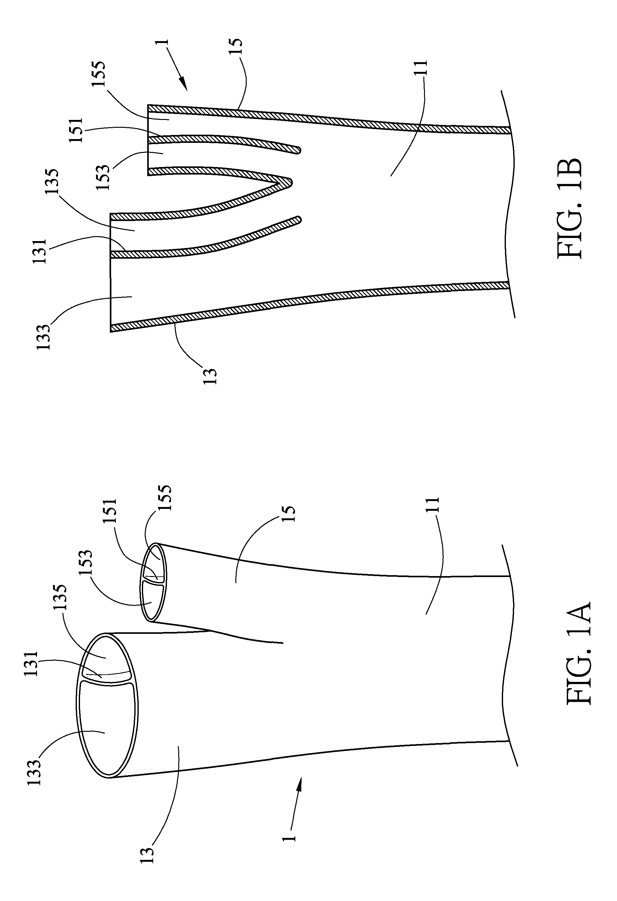
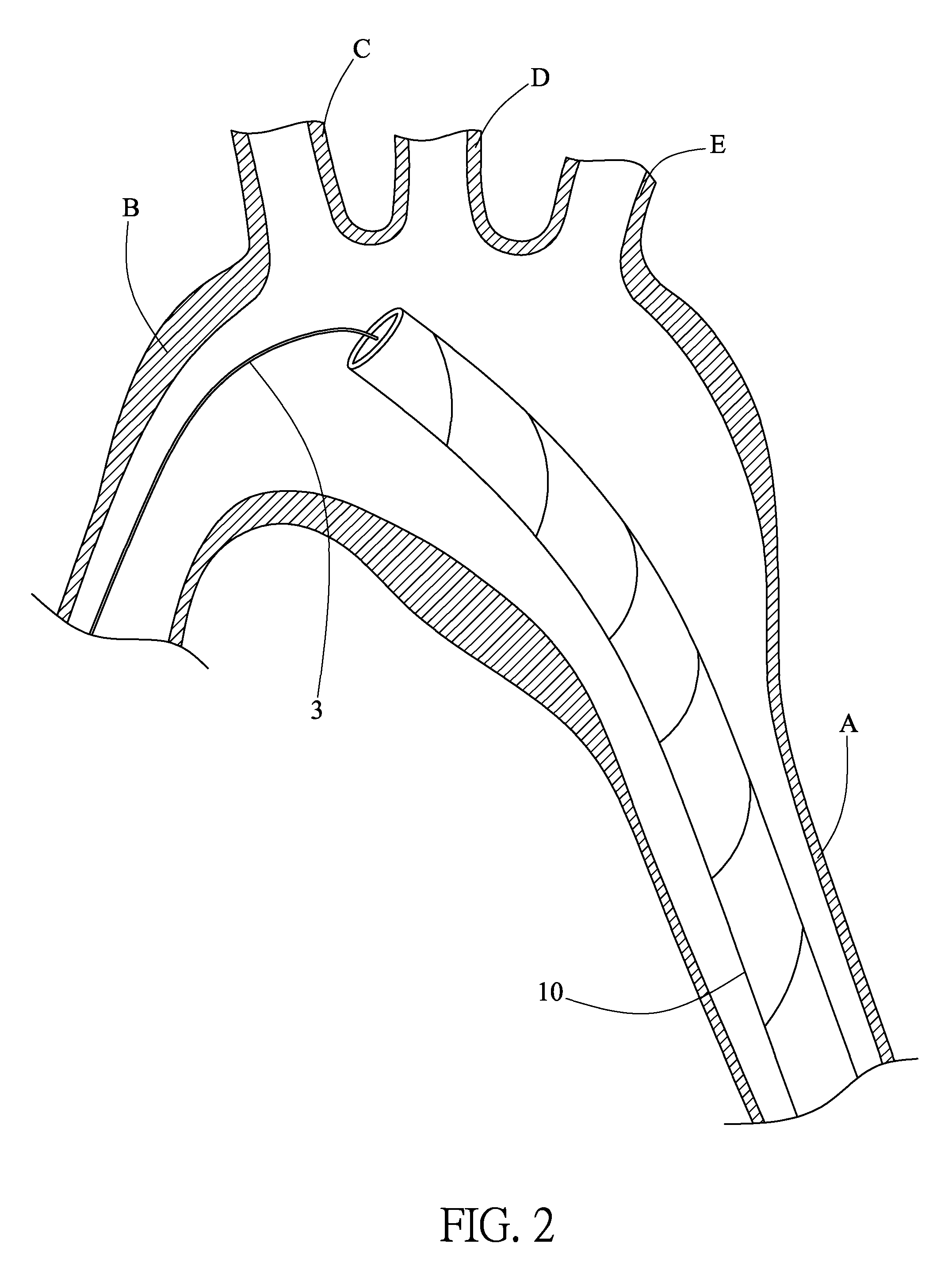
[0031]Referring to FIGS. 1 to 6, an aortic stent in accordance with the invention comprises the following components as discussed in detail below.

[0032]A main tube 1 is bifurcated and comprises a main section 11 having an outer diameter about equal to an inner diameter of a blood vessel of a descending aorta A, and first and second tube bifurcations 13, 15 branched from the main section 11. The first tube bifurcation 13 includes a first membrane 131 for dividing inside of the first tube bifurcation 13 into a first space 133 and a second space 135. Likewise, the second tube bifurcation 15 includes a second membrane 151 for dividing inside of the second tube bifurcation 15 into a third space 153 and a fourth space 155. It is noted that the first space 133 has an outer diameter, and said outer diameter of said first space 133, which corresponds to an inner diameter of an ascending aorta, is larger than outer diameters of the second space 135, the third space 153 and the fourth space 15...


PUM


Abstract

A method of implanting an aortic stent comprising steps of: putting a main tube on a metal guide wire; moving the main tube along the metal guide wire to the descending aorta, the main tube is constrained by a first cover, and first and second tube bifurcations are branched from the main section; removing the first cover; inserting a second and third metal guide wire through the first tube bifurcation into the ascending aorta and branchiocephalic artery respectively; a first and a second tube branch moving into the ascending aorta and the branchiocephalic artery respectively; inserting a fourth and fifth metal guide wire through the first tube bifurcation into the ascending aorta and branchiocephalic artery respectively; a third and a fourth tube branch moving into left common carotid artery and the left subclavian artery respectively; removing a second cover constraining said tube branches.

Description

CROSS-REFERENCED TO RELATED APPLICATIONS[0001]This application is a continuation-in-part of application Ser. No. 13 / 674,901 filed Nov. 12, 2012 entitled “Aortic Stent” and which is hereby incorporated herein by reference in its entirety.STATEMENT REGARDING FEDERALLY SPONSORED RESEARCH OR DEVELOPMENT[0002]Not applicableBACKGROUND OF THE INVENTION[0003]1. Field of the Invention[0004]The invention relates to stents and more particularly to a method of implanting an aortic stent.[0005]2. Description of Related Art[0006]A conventional aortic stent is shown in FIG. 7. And the main stent 7 is disposed from ascending aorta (AA). As shown in FIG. 7, the length of ascending aorta is short and does not have a sufficient space. Also, there is no securing device for the main stent 7 and the main stent 7 may be movable. More importantly, when the main stent 7 is secured, it also takes time to secure the branch grafts into branchiocephalic artery (BA), common carotid artery (CCA), left subclavian ...

Claims


Application Information

Patent Timeline
Patent Type & Authority Patents(United States)
IPC IPC(8): A61F2/06A61F2/07A61F2/852A61F2/856
CPCA61F2/07A61F2/852A61F2/856A61F2002/065A61F2230/001A61F2230/0034A61F2250/0039
Inventor HUNG, YEN-NIWU, MAO-TSUNYANG, CHEN
Owner VICTOR ACTION LTD
Why Eureka
Try Eureka