
Wave energy converter

a converter and wave energy technology, applied in the direction of water-power plants, motors, engine fuctions, etc., can solve the problems of low utilization rate, inefficient conversion of captured energy instantly, and great challenges that must be solved before wave power can be commercially viable, so as to reduce the drawbacks of prior art solutions, the effect of efficient power takeo

Inactive Publication Date: 2015-06-30
OCEAN HARVESTING TECH
View PDF73 Cites 2 Cited by
  • Summary
  • Abstract
  • Description
  • Claims
  • Application Information

AI Technical Summary

Benefits of technology

The present invention is about a new system for collecting and using wave energy. The system is designed to be efficient and easy to install and maintain, with a focus on the energy takeoff system. The invention avoids the problems of previous solutions and uses a hydraulic power takeoff system, which is more robust and flexible than other options. By arranging the energy absorption, accumulation, and power generation units in a floating body, the system is easy to install and maintain. Overall, the invention is designed to be the most effective and efficient way to use wave energy.

Problems solved by technology

However, there are great challenges that must be solved before wave power can be commercially viable.
Converting the captured energy instantly is not efficient.
The power will then fluctuate rapidly from zero up to the peak level which is not suitable from a conventional generator or the power grid to which it delivers the generated power.
The generator must be sized to handle the peaks of energy which will lead to low utilization and low electrical efficiency with high heat generation as a consequence.
However, compensating the damping of the generator to reduce the peak torques will reduce the electrical efficiency even further.
An alternative is to limit the maximum instantaneous energy capture or spill excessive energy captured but this will reduce the utilization of all other parts of the wave energy converter by reducing the average power output.
In hydraulic power takeoffs it is common to use gas accumulators, but the gas pressure and thereby the hydraulic pressure in the hydraulic system increases exponentially with the level of energy stored in the accumulator, making it difficult to achieve sufficient power smoothing without very large size of the gas accumulator.
Wave power technologies have been developed for a long period of time but up to now it has not been shown how to design a wave energy converter that is able to efficiently convert the intermittent and highly fluctuating energy form ocean waves into a steady power output, as described above.
However, this is not optimal for coupling a conventional generator to the anchor wheel to produce electric energy.
Then, the motive driving is only active during the rise of the wave and completely ceases when the wave sinks, this not being satisfactory.
However, changing the rotation direction of a mechanical transmission or of the generator twice in every wave period results in mechanical wear.
This gives high fluctuations in the power output and torque load in the system and as a consequence also low efficiency and utilization of the generator since the generator has to be oversized to handle the peak loads.
However, this only works optimally in the case where the buoys are evenly distributed over a wave period, which very seldom occurs since the length and the speed of the waves always vary.

Method used


Image

  • Wave energy converter
  • Wave energy converter
  • Wave energy converter

Examples


Embodiment Construction

[0028]In the following, a detailed description of various embodiments of a wave energy converter will be given. In this description, the term “pool of water” should be taken to include any body or mass of water.

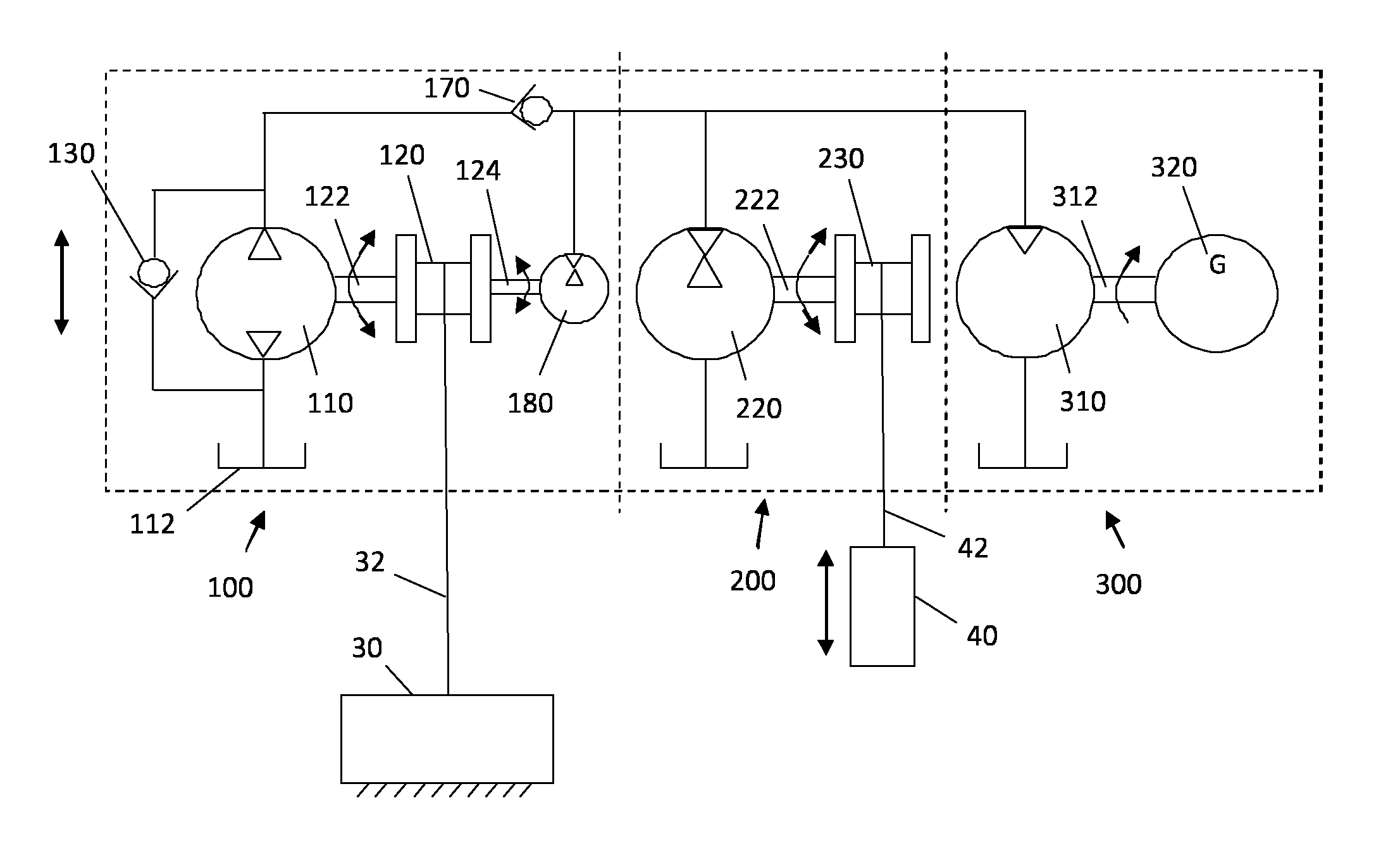
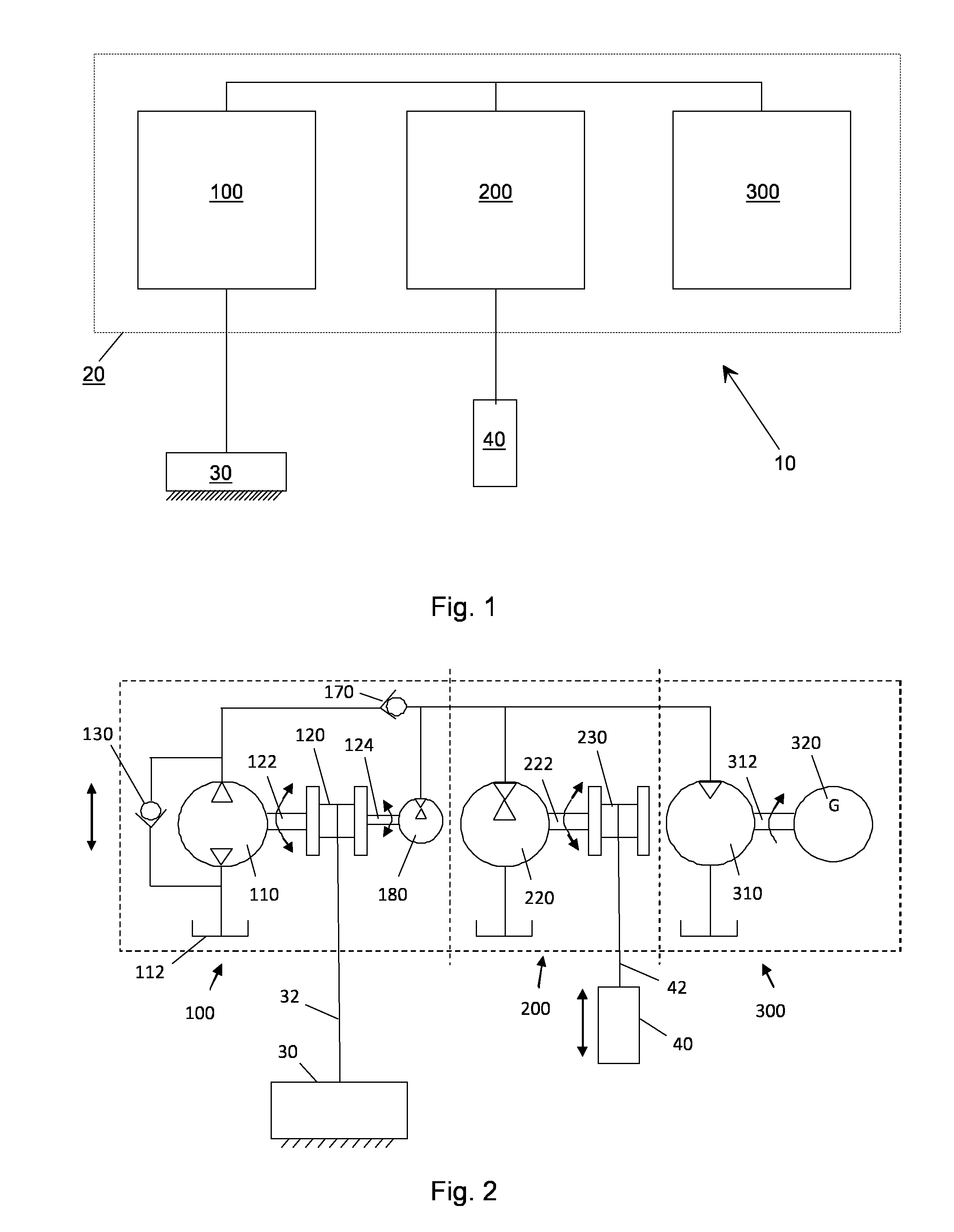
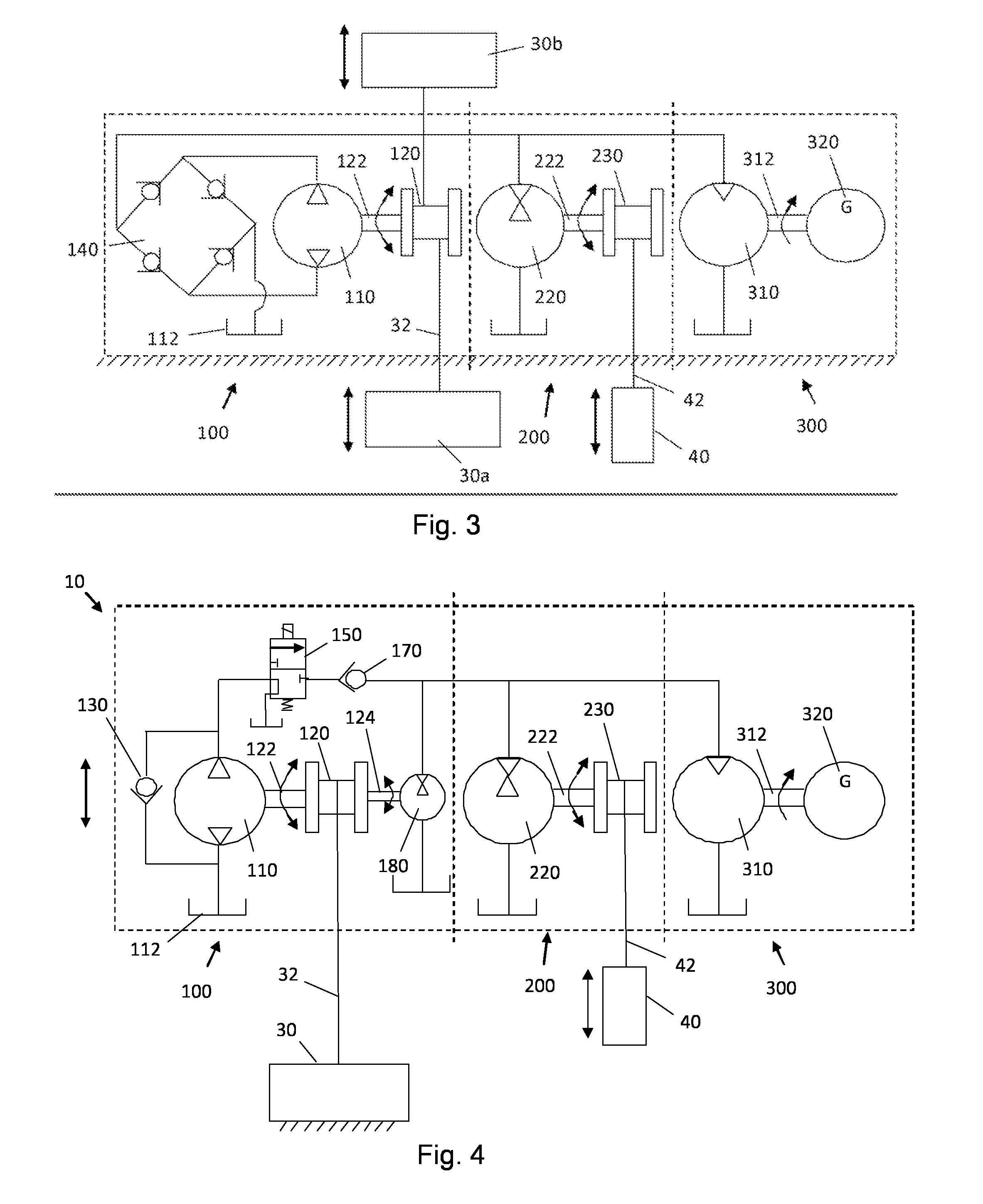
[0029]Referring to FIG. 1, a wave energy converter according to the invention comprises an energy absorption unit 100, an energy accumulation unit 200 connected to the energy absorption unit 100, and a power generation unit 300 connected to the energy absorption unit 100. These units are preferably arranged in a buoy or floating body 20.

[0030]The energy absorption unit 100 is arranged to absorb energy generated by movements of water when the wave energy converter is arranged in a pool of water. This can be achieved for example by an arrangement connecting the energy absorption unit to the seabed, for example a foundation 30, such as a bottom foundation, as will be explained in detail below. In the upward and downward movements of the water surface the buoy 20 is made to alter...


PUM


Abstract

A wave energy converter (10) comprises an energy absorption unit (100) arranged to absorb energy generated by movements of water when the wave energy converter is arranged in a pool of water, an energy accumulation unit (200) connected to the energy absorption unit, and a power generation unit (300) connected to the energy absorption unit. The energy accumulation unit is arranged to accumulate energy from the energy absorption unit when the energy absorption unit absorbs more power than the power generation unit generates and to dissipate energy to the power generation unit when the energy absorption unit absorbs less power than the power generation unit generates. By providing hydraulic components in these units, an efficient and flexible wave energy converter is provided.

Description

TECHNICAL FIELD[0001]The present invention relates to a wave energy converter for producing electric energy from movements of water waves, and a method of producing electric energy from more or less intermittent mechanical energy, such as more or less periodical movements of a body.BACKGROUND ART[0002]Wave energy is a concentrated form of renewable energy that comes from the friction between the water surface and the wind. The energy is built up by the wind on the open seas and then transported to locations closer to the shore, where it can be extracted with wave energy converters. Due to the high energy density of ocean waves, wave power is very area efficient and the average energy content changes more slowly and predictably compared to, for example, the wind. The resources are vast and can be harvested close to populated areas.[0003]However, there are great challenges that must be solved before wave power can be commercially viable. Intermittent and highly fluctuating energy from...

Claims


Application Information

Patent Timeline
Patent Type & Authority Patents(United States)
IPC IPC(8): F03B13/10H02P9/04F03B13/12F03B13/18F03G3/00F03B13/20E02B9/08
CPCF03B13/18F03B13/1885F03B13/20E02B9/08F03G3/00F05B2260/406Y02E10/38Y02E10/30
Inventor SIDENMARK, MIKAELANDERSSON, TORBJORN
Owner OCEAN HARVESTING TECH
Learn More