Electric connector for cooling a compressor drive circuit

a technology of electric connectors and compressors, which is applied in the direction of positive displacement liquid engines, pumping waves, and pumping pumps, etc., can solve the problems of reducing the amount of cooling, deteriorating cooling performance of the inverter, and hindering the efficient cooling of the bottom by the refrigerant, so as to achieve the effect of improving cooling performan

Inactive Publication Date: 2015-06-30
TOYOTA IND CORP
View PDF21 Cites 5 Cited by
  • Summary
  • Abstract
  • Description
  • Claims
  • Application Information

AI Technical Summary

Benefits of technology

[0010]Accordingly, it is an objective of the present invention to provide a motor-driven compressor that improves cooling performance for a drive circuit.
[0012]In accordance with a second aspect of the present invention, a motor-driven compressor is provided that includes a housing, a partition defining inside the housing a first area and a second area, which are isolated from each other, a compressing portion, an electric motor, a drive circuit, a conductive member, and an electrical connection portion. The compressing portion and the electric motor are accommodated in the first area. The electric motor is a drive source of the compressing portion. The drive circuit drives the electric motor, and is arranged in the second area so as to have dissipation of the drive circuit. The conductive member is electrically connected to the drive circuit and is fixed to the partition. The electrical connection portion electrically connects the conductive member and the electric motor to each other. A part of the electrical connection portion is received in a passing area formed between the housing and the compressing portion. The housing has a suction port and a discharge port. The discharge port is located at a position that is farther from the partition than the suction port and the passing area. An insertion member is located in the passing area. After refrigerant is discharged from the compressing portion, the insertion member increases flow of refrigerant toward the discharge port by restricting flow of refrigerant toward the partition via the passing area.

Problems solved by technology

This reduces the amount of refrigerant flowing toward the bottom of the motor housing member, which hinders efficient cooling of the bottom by the refrigerant.
As a result, the cooling performance for the inverter deteriorates.
Such a problem is substantially common to any type of motor-driven compressors having a passing area that receives a part of an electrical connection portion for electrically connecting a conductive member with an electric motor.
In this case, some high-temperature and high-pressure refrigerant, which is generated through compression in the compressing portion, flows toward the partition through the passing area to undesirably warm the partition.
As a result, the cooling performance for the inverter deteriorates.

Method used


Image

  • Electric connector for cooling a compressor drive circuit
  • Electric connector for cooling a compressor drive circuit
  • Electric connector for cooling a compressor drive circuit

Examples


first embodiment

[0025]A first embodiment of the present invention will now be described with reference to FIGS. 1 to 3.

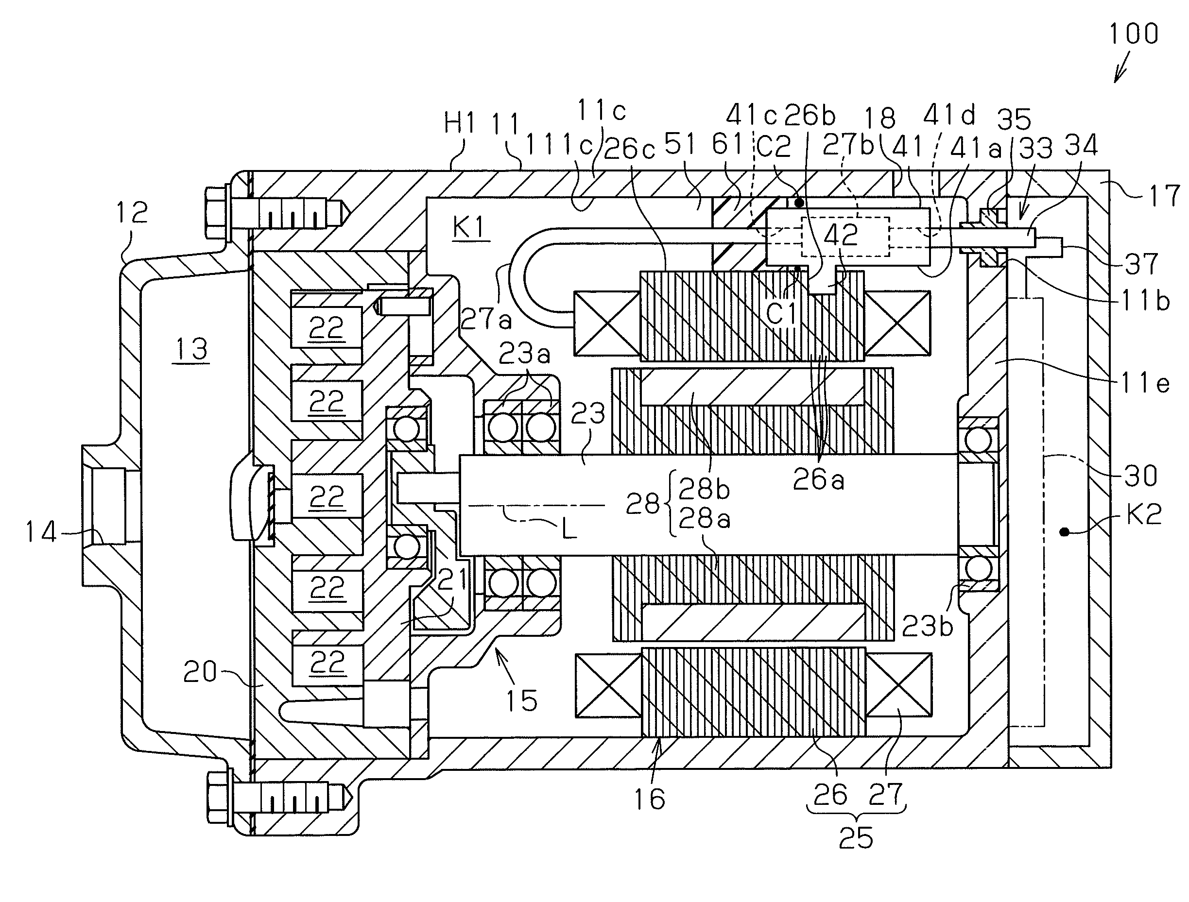
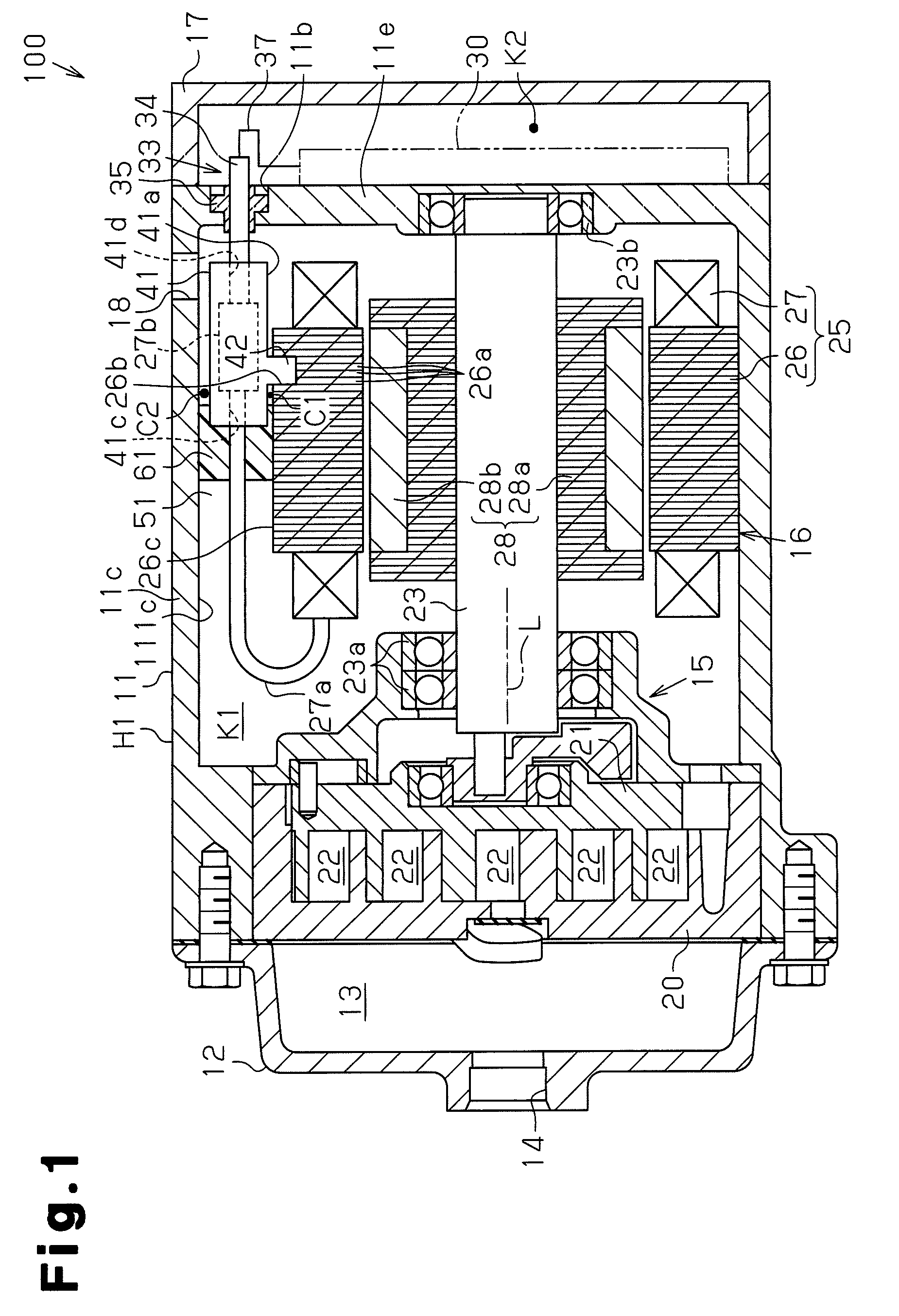
[0026]As shown in FIG. 1, a motor-driven compressor 100 includes a cylindrical suction housing member 11, which is made of metal and has a closed end, and a discharge housing member 12 joined to the open end (left end as viewed in FIG. 1) of the suction housing member 11. The discharge housing member 12 is also made of metal and has a closed end. A discharge chamber 13 is defined between the suction housing member 11 and the discharge housing member 12. An inverter housing member 17, which is made of metal, is joined to a bottom wall 11e of the suction housing member 11. In the present embodiment, the suction housing member 11, the discharge housing member 12, and the inverter housing member 17 are made of aluminum. The suction housing member 11, the discharge housing member 12, and the inverter housing member 17 form a housing H1 of the motor-driven compressor 100 according to the...

second embodiment

[0054]A second embodiment of the present invention will now be described with reference to FIG. 4. In the following description, like or the same reference numerals are given to those components that are like or the same as the corresponding components of the first embodiment and detailed explanations are omitted or simplified.

[0055]As shown in FIG. 4, a motor-driven compressor 70 includes a cylindrical first housing member 71, which is made of metal and has a closed end, and a second housing member 72 joined to the open end (left end as viewed in FIG. 4) of the first housing member 71. The second housing member 72 is also made of metal and has a closed end. An inverter housing member 73, which is made of metal, is joined to a bottom wall 72e of the second housing member 72. In the present embodiment, the first housing member 71, the second housing member 72, and the inverter housing member 73 are made of aluminum. The first housing member 71, the second housing member 72, and the i...


PUM


Abstract

A motor-driven compressor has a housing and a partition. A compressing portion and an electric motor as the drive source of the compressing portion are accommodated in a first area. A drive circuit for the motor is arranged in a second area so as to have dissipation of the drive circuit. The compressor further includes a conductive member electrically connected to the circuit and fixed to the partition, and an electrical connection portion electrically connecting the conductive member to the motor. The connection portion is partly received in a passing area formed between the housing and the motor. The housing has a suction port and a discharge port. The discharge port is located at a position farther from the partition than the suction port and the passing area. An insertion member in the passing area restricts flow of refrigerant in the housing toward the discharge port via the passing area.

Description

BACKGROUND OF THE INVENTION[0001]The present invention relates to a motor-driven compressor.[0002]Japanese Laid-Open Patent Publication No. 2010-59809 discloses a motor-driven compressor that includes a compressing portion for compressing and discharging refrigerant, an electric motor for driving the compressing portion, and an inverter (drive circuit) for actuating the electric motor. The motor-driven compressor disclosed in Japanese Laid-Open Patent Publication No. 2010-59809 includes a motor housing member and a front housing member, which is secured to the front side of the motor housing member. The electric motor and the compression portion are accommodated in the area between the motor housing member and the front housing member. An inverter housing member is secured to a bottom (partition), which is at the rear of the motor housing member. An inverter accommodating chamber is defined between the bottom of the motor housing member and the inverter housing member. The inverter ...

Claims


Application Information

Patent Timeline
Patent Type & Authority Patents(United States)
IPC IPC(8): F04D35/00F04C15/00F04C29/00F04D25/06F04D29/58F04B17/03F04C23/00F04C29/04F04B39/06F04B53/06F04B35/04F04B53/08F04C18/02
CPCF04B17/03F04C15/0096F04B39/066F04B53/06F04D29/5813F04B35/04F04D25/0606F04B53/08F04C2240/403F04C29/0007F04C23/008F04C29/047F04C18/0215F04C2240/803F04C2240/808
Inventor FUKASAKU, HIROSHI
Owner TOYOTA IND CORP
Why Eureka
Try Eureka