Magnetic stud fastener finder

a magnetic stud and finder technology, applied in the field of magnetic stud finders, can solve the problems of tracing being difficult to accurately locate, affecting the accuracy of drywall installation, so as to achieve the effect of easy viewing

Active Publication Date: 2015-06-30
EBNER EMMETT J +1
View PDF23 Cites 14 Cited by
  • Summary
  • Abstract
  • Description
  • Claims
  • Application Information

AI Technical Summary

Benefits of technology

[0013]The stud finder may provide a reliable, easy to use, and inexpensive stud finding tool. Along these lines, the stud finder may not require expensive electrical components, which would otherwise be found in more costly electronic stud finding tools. Furthermore, the stud finder is configured to reliably determine the location of the stud by determining the presence of metallic objects disposed within the stud. Therefore, the stud finder provides a simple and cost-effective solution to the above-described deficiencies associated with conventional stud finding equipment.
[0015]The body may be formed from a transparent material to allow a user to easily view the magnetic element disposed therein as it moves within the internal compartment. The body may also extend in a longitudinal direction to define a length which is approximately equal to sixteen inches, which is similar to the distance between adjacent studs according to standard construction guidelines.

Problems solved by technology

If the hardware is not driven into the studs, the picture or shelves may fall from the wall.
While this solution helped to locate the studs, the tracing could often be very time-consuming and lack the accuracy required for proper drywall installation.
However, this technique would generally be tedious, time consuming, and generally results in several holes formed within the drywall.
Although electronic stud finders may provide certain benefits relative to the earliest stud finding techniques, electronic stud finders generally suffer from several deficiencies.
One deficiency is the cost associated therewith.
The components typically included in the electrical stud finders, such as electrical circuitry, power sources, indication means, etc., generally results in a higher cost, particularly relative to the cost associated with the earlier stud finding techniques.
Another deficiency associated with electronic stud finders is that they may not accurately indicate the position of the stud located behind a wall.
For instance, the wall may include wiring, plumbing and other support structures which may interfere with the electronic stud finder's search for the stud.

Method used


Image

  • Magnetic stud fastener finder
  • Magnetic stud fastener finder
  • Magnetic stud fastener finder

Examples


Embodiment Construction

[0023]The detailed description set forth below is intended as a description of the presently preferred embodiment of the invention, and is not intended to represent the only form in which the present invention may be constructed or utilized. The description sets forth the functions and sequences of steps for constructing and operating the invention. It is to be understood, however, that the same or equivalent functions and sequences may be accomplished by different embodiments and that they are also intended to be encompassed within the scope of the invention.

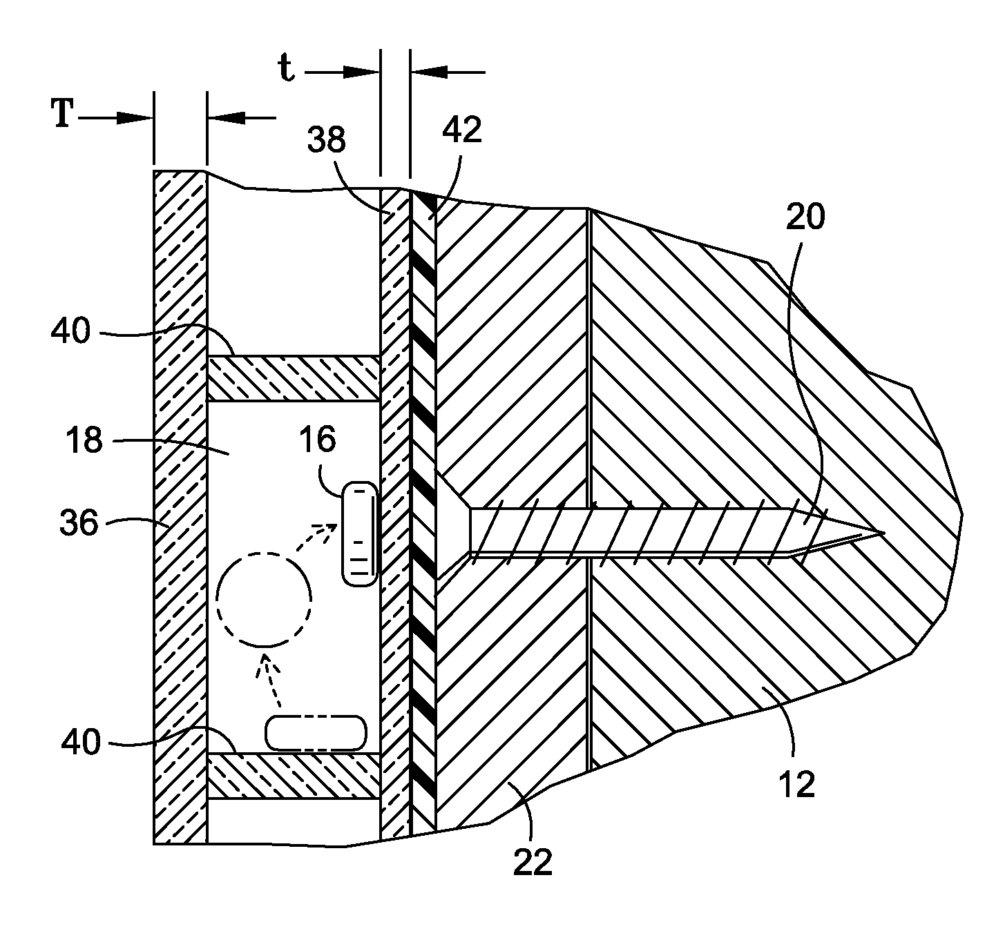
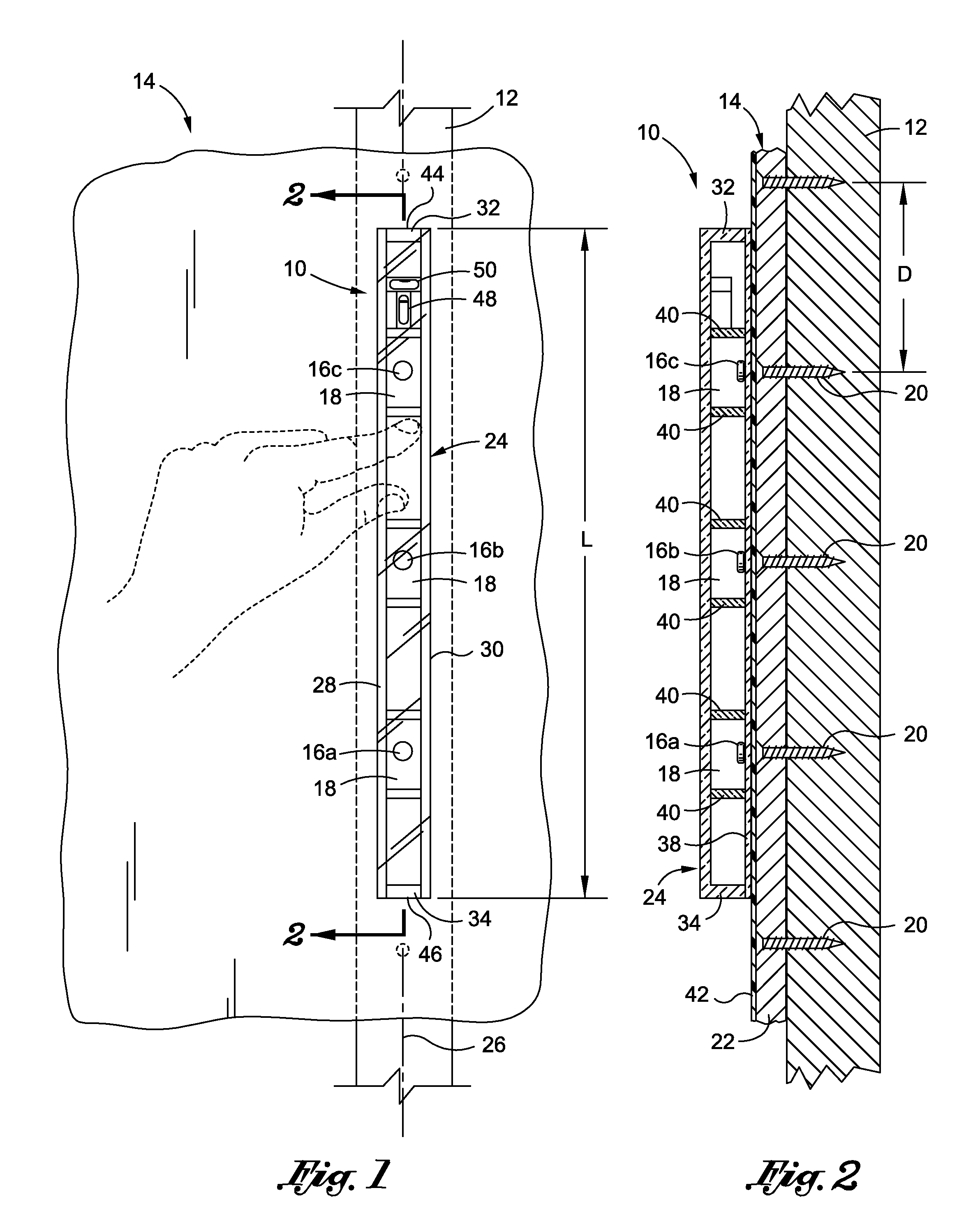
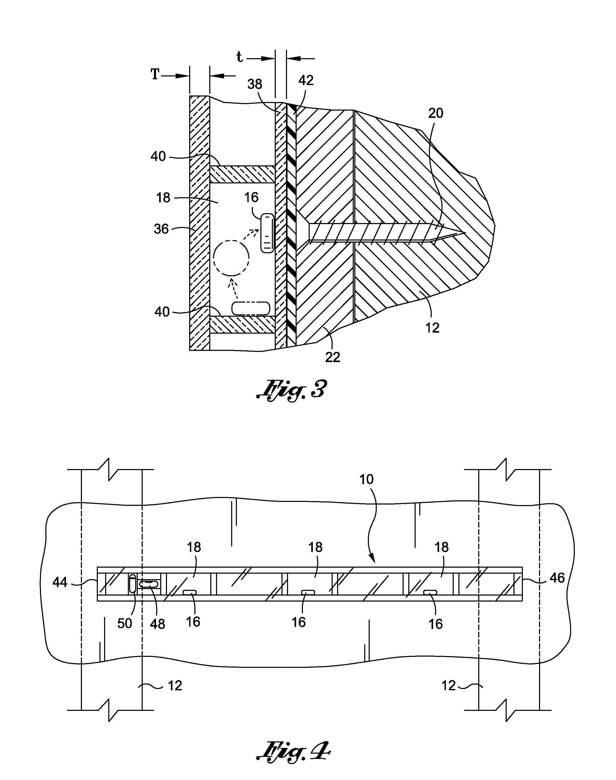
[0024]Referring now to the drawings, wherein the showings are for purposes of illustrating a preferred embodiment of the present invention only, and not for purposes of limiting the same, there is shown a stud finder 10 configured to identify the location of a stud 12 behind a wall 14. The stud finder 10 includes a magnetic element 16 disposed within an internal compartment 18 of the stud finder 10, wherein the magnetic element...


PUM


Abstract

Provided is a stud finder for determining the location of a stud within a wall. The stud finder includes a body having an internal compartment formed therein which is sized and configured to house a magnetic element therein. The stud finder is moveable along the wall to place the magnetic element in magnetic attraction with metallic fasteners (i.e., nails, screws, etc) disposed within the stud, such as for securing drywall to the stud. The magnetic attraction urges the magnetic element toward the metallic element to provide a visual indication as to the precise location of the metallic element, as well as the underlying stud.

Description

CROSS-REFERENCE TO RELATED APPLICATIONS[0001](Not Applicable)STATEMENT RE: FEDERALLY SPONSORED RESEARCH / DEVELOPMENT[0002](Not Applicable)BACKGROUND OF THE INVENTION[0003]1. Field of the Invention[0004]The present invention relates generally to a stud finder, and more specifically to a stud finding device having a magnetic element disposed within an internal compartment.[0005]2. Description of the Related Art[0006]In both residential and commercial building construction, drywall or another similar wall forming material is typically secured to support studs via mechanical fasteners, such as nails or screws. The mechanical fasteners are oftentimes concealed by putty or other material to give the appearance of a continuous wall surface.[0007]On occasion, it is to locate the studs beneath the walls or roofs and the like. Along these lines, it may be important, if not critical, to locate a structural stud member to perform even the simple task of hanging a picture or installing a new set ...

Claims


Application Information

Patent Timeline
Patent Type & Authority Patents(United States)
IPC IPC(8): G01R33/00
CPCG01R33/007G01R33/0076
Inventor EBNER, EMMETT J.HUFFER, BRIAN J.
Owner EBNER EMMETT J
Why Eureka
Try Eureka