
Anti-reflective coating for photolithography and methods of preparation thereof

a technology of anti-reflective coating and photolithography, which is applied in the direction of photomechanical equipment, instruments, transportation and packaging, etc., can solve the problems of limiting usable process sequences, affecting introducing new challenges in the manufacture of devices with smaller feature sizes. achieve the effect of improving the compatibility or physical quality of the resulting film, improving the etch selectivity and/or stripping selectivity, and minimizing the effect o

Active Publication Date: 2015-06-30
HONEYWELL INT INC
View PDF545 Cites 17 Cited by
  • Summary
  • Abstract
  • Description
  • Claims
  • Application Information

AI Technical Summary

Benefits of technology

[0013]An anti-reflective coating material for ultraviolet photolithography comprises at least one inorganic-based compound; at least one absorbing compound and at least one material modification agent. The at least one material modification agent may include any compound or composition that can modify the coating material to improve the photolithographic, compatibility or physical quality of the resulting film, such as by improving the etch selectivity and / or stripping selectivity or by minimizing the fill bias. The at least one material modification agent may comprise at least one porogen, at least one high-boiling solvent, at least one catalyst, at least one leveling agent, at least one pH tuning agent, at least one replacement solvent, at least one capping agent, at least one adhesion promoter, such as a resin-based material and / or a combination thereof that are incorporated into the inorganic-based material or compound. Resin-based adhesion promoters may comprise phenolic-containing resins, novolac resins, such as CRJ-406 or HRJ-11040 (both from Schenectady International, Inc.), an organic acrylate resin and / or a styrene resin. Other adhesion promoters may comprise polydimethylsiloxane materials, ethoxy or hydroxy-containing silane monomers, vinyl-containing silane monomers, acrylated silane monomers, or silyl hydrides.
[0016]As mentioned, at least one material modification agent, such as at least one porogen, at least one high-boiling solvent, at least one catalyst, at least one pH tuning agent, at least one capping agent, at least one replacement solvent, at least one leveling agent, at least one adhesion promoter, such as a resin-based material and / or a combination thereof that are incorporated into the inorganic-based material or compound. Resin-based adhesion promoters may comprise phenolic-containing resins, novolac resins, such as CRJ-406 or HRJ-11040 (both from Schenectady International, Inc.), an organic acrylate resin and / or a styrene resin. Other adhesion promoters may comprise polydimethylsiloxane materials, ethoxy or hydroxy-containing silane monomers, vinyl-containing silane monomers, acrylated silane monomers, or silyl hydrides. The material modification agent, whether it is the porogen, the high-boiling solvent the catalyst, the leveling agent, the pH tuning agent, the one replacement solvent, the capping agent, the one adhesion promoter and / or a combination thereof is added in order to modify or adjust the anti-reflective coating material in order to meet the design goals of the component or layered material being manufactured. More specifically, the material modification agent will a) increase the etch selectivity and / or strip rate of the coating material; b) minimize the fill bias and / or voiding in the via structures; and / or c) reduce resist “fall over” once a pattern has been developed in the resist.

Problems solved by technology

Manufacturing of devices with smaller feature sizes introduces new challenges in many of the processes conventionally used in semiconductor fabrication.
It has long been recognized that linewidth variations in patterns produced by photolithography can result from optical interference from light reflecting off an underlying layer on a semiconductor wafer.
However, the fact that the organic ARC's share many chemical properties with the organic photoresists can limit usable process sequences.
Even though these previous patents may address some of the issues with intermixing, the problem of the lack of 86- to 90-degree uniformity on the resist edges because of the coupled ARC layer has not been addressed in the prior art.
In other words, the patterned resist sidewall can't maintain an approximate 90-degree angle with respect to the anti-reflective coating after photoresist developing.
Photoresists and anti-reflective coatings can also have substandard or unacceptable, etch selectivity or stripping selectivity.
Poor etch selectivity and / or stripping selectivity can lead to low etch rates for the film.
Poor etch selectivity can also lead to poor transfer of critical dimensions from the printing step(s) through the etch step(s).
However, the etch selectivity obtained with these reactive compounds are not sufficient for most photoresists and anti-reflective coatings and require additional chemical reaction steps that may not be necessary.
In addition, photoresists and anti-reflective coatings often have difficulty with fill bias and voiding in via structures to the point where any planarization of the surface is severely compromised.
If the ARC coating is organic, such a thick coating will further compromise the accurate transfer of the as patterned critical dimension through the film stack.
However, the spin-on-glass, dye combinations that have been disclosed to date are not optimal for exposure to the deep ultraviolet, particularly 248 and 193 nm, light sources that are coming into use to produce devices with small feature sizes.
Furthermore, not all dyes can be readily incorporated into an arbitrary spin-on-glass composition.
Also, even though these ARC's are chemically different than the previously mentioned organic ARC's, the coupled resist layers can still suffer from “falling over” after being developed, as based on the chemical, physical, and mechanical incompatibility of the ARC layer and the resist layer—which is a common problem when trying to couple resist materials and anti-reflective coatings.

Method used


Image

  • Anti-reflective coating for photolithography and methods of preparation thereof
  • Anti-reflective coating for photolithography and methods of preparation thereof
  • Anti-reflective coating for photolithography and methods of preparation thereof

Examples


example 1

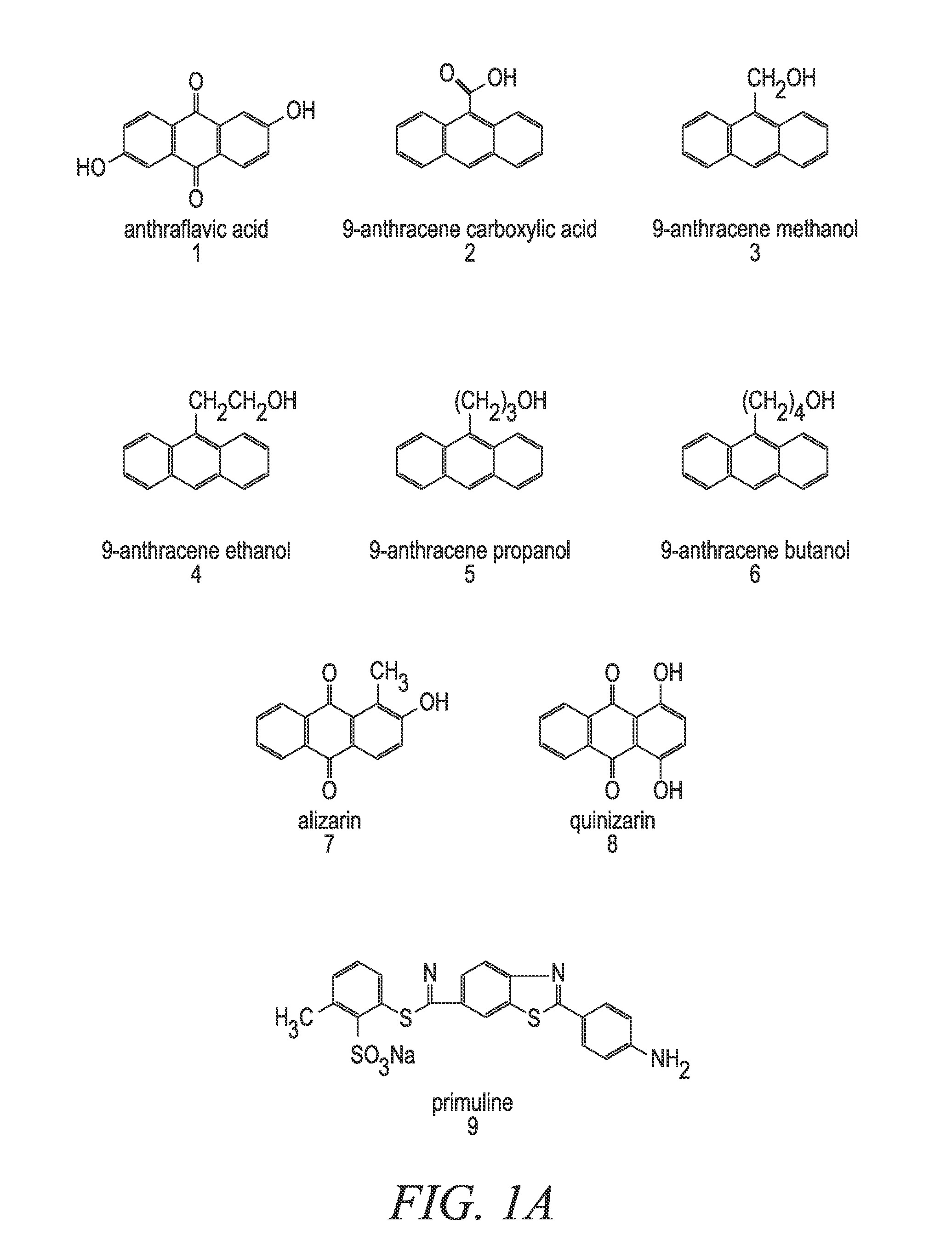
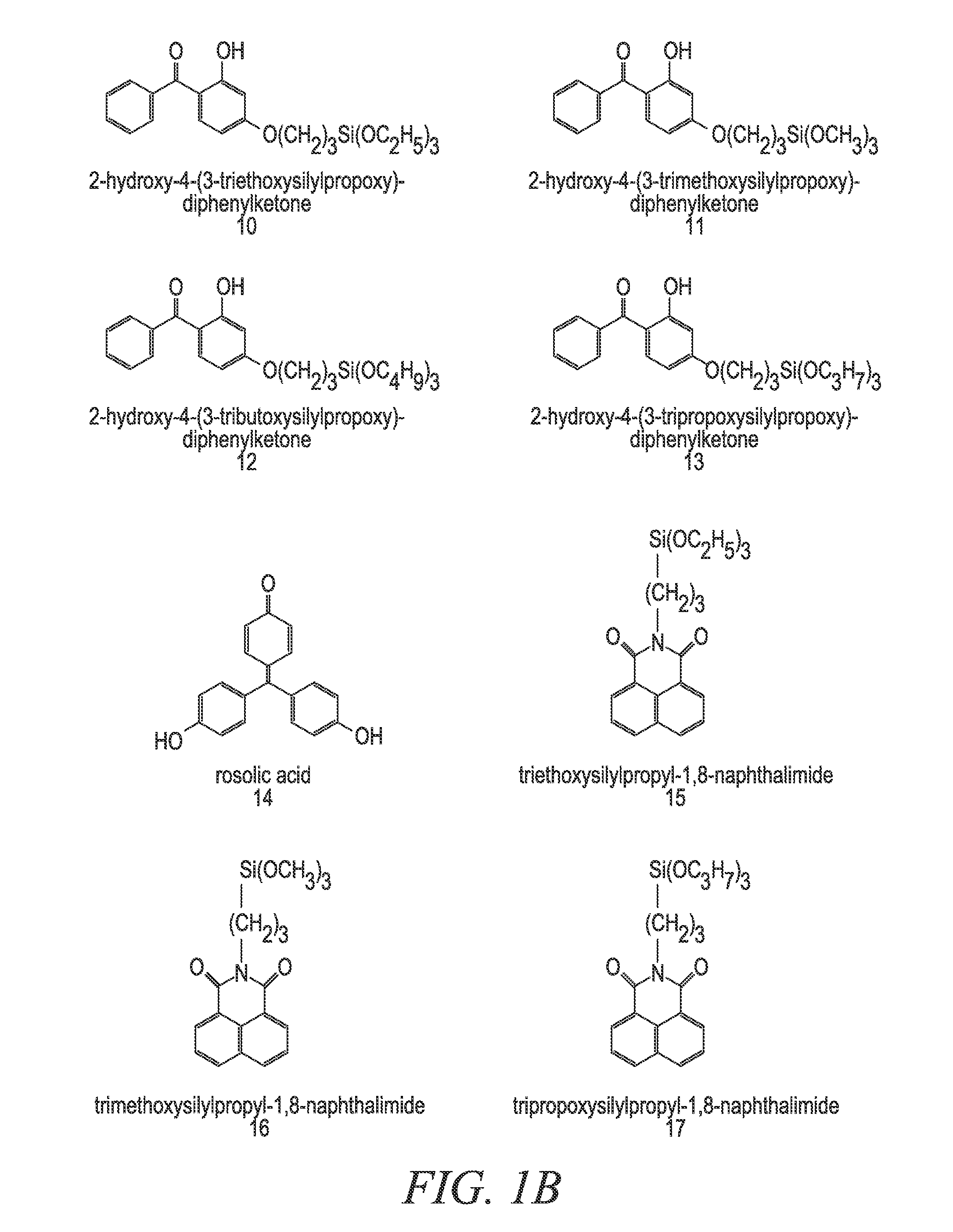
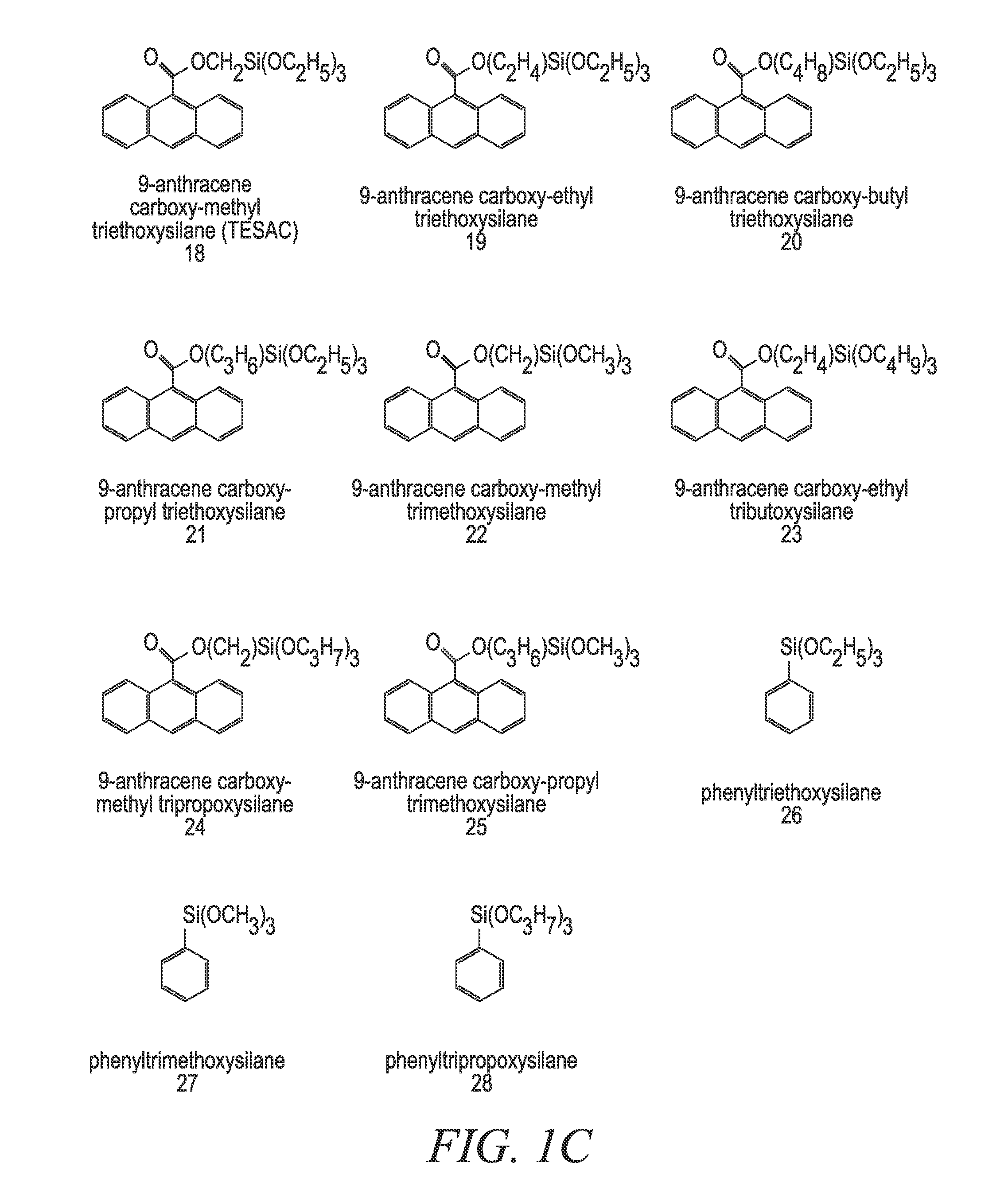
[0172]In a 22-liter flask 6497.86 grams solvent, 2633.78 grams TEOS, 1639.78 grams MTEOS, 958.97 grams 9-anthracene carboxy-methyl triethoxysilane, 119.24 grams 0.1 M nitric acid and 1425.58 grams deionized water were combined. The flask was refluxed and / or heated for 1 to 12 hours. To the solution, 932.80 grams of butanol and 20650.0 g of ethyl lactate was added. The acetone alone or the 2-propanol / acetone mixture that would have normally been used in the reaction is replaced with at least one replacement solvent. In one embodiment, a 2:1 mixture of ethanol / PGMEA is used as the at least one replacement solvent. In another embodiment, a 2:1 mixture of PGMEA / ethanol is used as the at least one replacement solvent. It is important to note that any of the compounds and / or mixtures found in Examples 6-21 can be substituted for the above-referenced compound. It is also important to note that even though Examples 6-21 deal with absorbing compounds and pH tuning agent addition, the pH tuni...

example 2

[0176]In a 22-liter flask 6331.20 grams 2-propanol, 3166.66 grams solvent, such as acetone, 2633.78 grams TEOS, 1639.78 grams MTEOS, 958.97 grams 9-anthracene carboxy-methyl triethoxysilane, 119.24 grams 0.1 M nitric acid and 1425.58 grams deionized water were combined. The flask was refluxed and / or heated for 1 to 12 hours. To the solution, 932.80 grams of butanol and 20650.0 g of ethyl lactate was added. The material modification agent added for this set of examples was the at least one high boiling solvent, which was in this case glycerol. For this set of experimental data, 1% glycerol was added to the mixture to eliminate voiding and to improve the % via fill in the absorbing composition coating material. It is important to note that any of the compounds and / or mixtures found in Examples 6-21 can be substituted for the above-referenced compound. It is also important to note that even though Examples 6-21 deal with absorbing compounds and pH tuning agent addition, the pH tuning a...

example 3

[0178]In a 22-liter flask 6331.20 grams 2-propanol, 3166.66 grams acetone, 2633.78 grams TEOS, 1639.78 grams MTEOS, 958.97 grams 9-anthracene carboxy-methyl triethoxysilane, 119.24 grams 0.1 M nitric acid and 1425.58 grams deionized water were combined. The flask was refluxed and / or heated for 1 to 12 hours. The heating / refluxing time was divided into four relatively equal time intervals, and at each time interval TMEOS was added in 0.2 g, 0.5 g, 1 g and 5 g amounts respectively. To the solution, 20650.0 g of ethyl lactate was added. Also, in some of the embodiments 932.80 grams of butanol was added after the TMEOS addition was completed. The material modification agent added for this set of examples was the at least one capping agent, which was in this case TMEOS. It is important to note that any of the compounds and / or mixtures found in Examples 6-21 can be substituted for the above-referenced compound. It is also important to note that even though Examples 6-21 deal with absorbin...


PUM

PropertyMeasurementUnit
wavelengthsaaaaaaaaaa

Abstract

Anti-reflective coating materials for ultraviolet photolithography include at least one absorbing compound and at least one material modification agent, such as at least one porogen, at least one high-boiling solvent, at least one capping agent, at least one leveling agent, at least one catalyst, at least one replacement solvent, at least one pH tuning agent, and / or a combination thereof that are incorporated into inorganic-based materials or inorganic compositions and / or compounds. Suitable absorbing compounds are those that absorb around wavelengths such as 365 nm, 248 nm, 193 nm and 157 nm that may be used in photolithography.

Description

CROSS-REFERENCE TO RELATED APPLICATIONS[0001]This application is a national stage application of PCT / US02 / 36327, filed Nov. 12, 2002, which is a continuation application of U.S. patent application Ser. No. 10 / 001,143, filed Nov. 15, 2001, which issued as U.S. Pat. No. 6,824,879 on Nov. 30, 2004, which is a continuation-in-part application of U.S. patent application Ser. No. 09 / 698,883, filed Oct. 27, 2000, which issued as U.S. Pat. No. 6,365,765 on Apr. 2, 2002, which is a continuation-in-part application of U.S. patent application Ser. No. 09 / 491,166, filed Jan. 26, 2000, which issued as U.S. Pat. No. 6,506,497 on Jan. 15, 2003, which is a continuation-in-part application of U.S. patent application Ser. No. 09 / 330,248, filed Jun. 10, 1999, which issued as U.S. Pat. No. 6,268,457 on Jul. 31, 2001.FIELD OF THE INVENTION[0002]The present invention relates generally to anti-reflective coating materials and more specifically to anti-reflective layers for use in photolithography and meth...

Claims


Application Information

Patent Timeline
Patent Type & Authority Patents(United States)
IPC IPC(8): C08G77/26C09D183/06C09D183/04C08K5/00C08G77/12C08G77/04C03C17/30C03C17/00G02B5/23C09D183/08G03F7/09H01L21/027G03F7/075C07F7/18C08L83/00C08L101/00C09D5/00C09D7/12G02B1/11G03F7/11
CPCG02B5/23C03C17/008C03C17/30C08G77/04C08G77/12C08K5/0008C09D183/04C09D183/06C09D183/08G03F7/091C08L83/04H01L21/0276C08L2666/28Y10T428/31663G03F7/075
Inventor BALDWIN, TERESAKENNEDY, JOSEPHIWAMOTO, NANCYNAKANO, TADASHIBEDWELL, WILLIAMSTUCK, JASONSUEDEMEYER, ARLENEHEBERT, MELLO
Owner HONEYWELL INT INC
Learn More