Method of attaching a magnet to a rotor or a stator of an electrical machine

a technology of electrical machines and magnets, which is applied in the direction of dynamo-electric machines, wind energy generation, magnetic circuit shapes/forms/construction, etc., can solve the problems of inflexible and expensive approach, insufficient protection against corrosion or mechanical impact, and additional weight contribution of steel bars, etc., to achieve the effect of not leaving too much leeway

Inactive Publication Date: 2015-06-30
SIEMENS AG
View PDF18 Cites 1 Cited by
  • Summary
  • Abstract
  • Description
  • Claims
  • Application Information

AI Technical Summary

Benefits of technology

[0008]An obvious advantage of the invention is that, because a pair of retainers is used for the fixation of a magnet, these can be manufactured in a much more straightforward manner than the single prior art U-shaped housing, which must be shaped precisely to fit over the magnet while not leaving too much leeway. Furthermore, the retainers according to the invention need not be soldered into place. Instead, the vacuum consolidation step ensures they are effectively glued to the magnet and to the rotor / stator.
[0009]According to the invention, the magnet mounting arrangement for a rotor or a stator of an electrical machine comprises a magnet arranged along an outside surface of the rotor or stator; a pair of retainers arranged one on each side of the magnet; and an adhesive layer bonding the retainers to the magnet.
[0010]According to the invention, the generator comprises a rotor and a stator, wherein the rotor comprises such a magnet mounting arrangement.
[0011]According to the invention, the wind turbine comprises such a generator.
[0012]Particularly advantageous embodiments and features of the invention are given by the dependent claims, as revealed in the following description. Features of the different embodiments can be combined as appropriate to give further embodiments.
[0013]The field of an electrical machine can be the rotor or the stator, depending on the way in which the electric machine—for example a generator—is constructed. Usually, however, particularly in large generators, the rotor is the field and bears the magnets, while the stator is the armature and carries the coil windings. Therefore, in the following but without restricting the invention in any way, it is assumed that the electrical machine is a generator and that the magnets are mounted on the rotor, although the method according to the invention for determining a magnet arrangement would be equally applicable to a realisation in which the magnets are mounted on the stator. Here, the term ‘surface of the rotor’ is to mean the appropriate surface of the rotor to which the magnets are attached. For an electrical machine with the rotor on the outside, enclosing the stator, the magnets will generally be mounted on the interior surface of the rotor to face the stator across an air gap. For an electrical machine with the rotor on the inside and the stator on the outside, the magnets will generally be mounted on the exterior surface of the rotor to face the stator across the air gap. Magnets (or ‘poles’) are generally rectangular in shape and are attached along their length on the surface of the rotor in a direction parallel to the rotational axis of the rotor. In the following, the term ‘upper face of a magnet’ is to be understood to mean the face of the magnet opposite to the magnet face that is attached to the rotor / stator. A ‘side face’ of a magnet is to be understood to mean a face that is essentially perpendicular to the rotor / stator.

Problems solved by technology

However, this approach is inflexible and expensive, since it requires a steel base for each magnet, a closely-fitting housing for each magnet, and a time-consuming soldering step.
Another disadvantage is the additional weight contribution on account of the steel bars.
While this solution is considerably more economical than the other prior art technique, it does not provide satisfactory protection against corrosion or mechanical impact.

Method used


Image

  • Method of attaching a magnet to a rotor or a stator of an electrical machine
  • Method of attaching a magnet to a rotor or a stator of an electrical machine
  • Method of attaching a magnet to a rotor or a stator of an electrical machine

Examples


Embodiment Construction

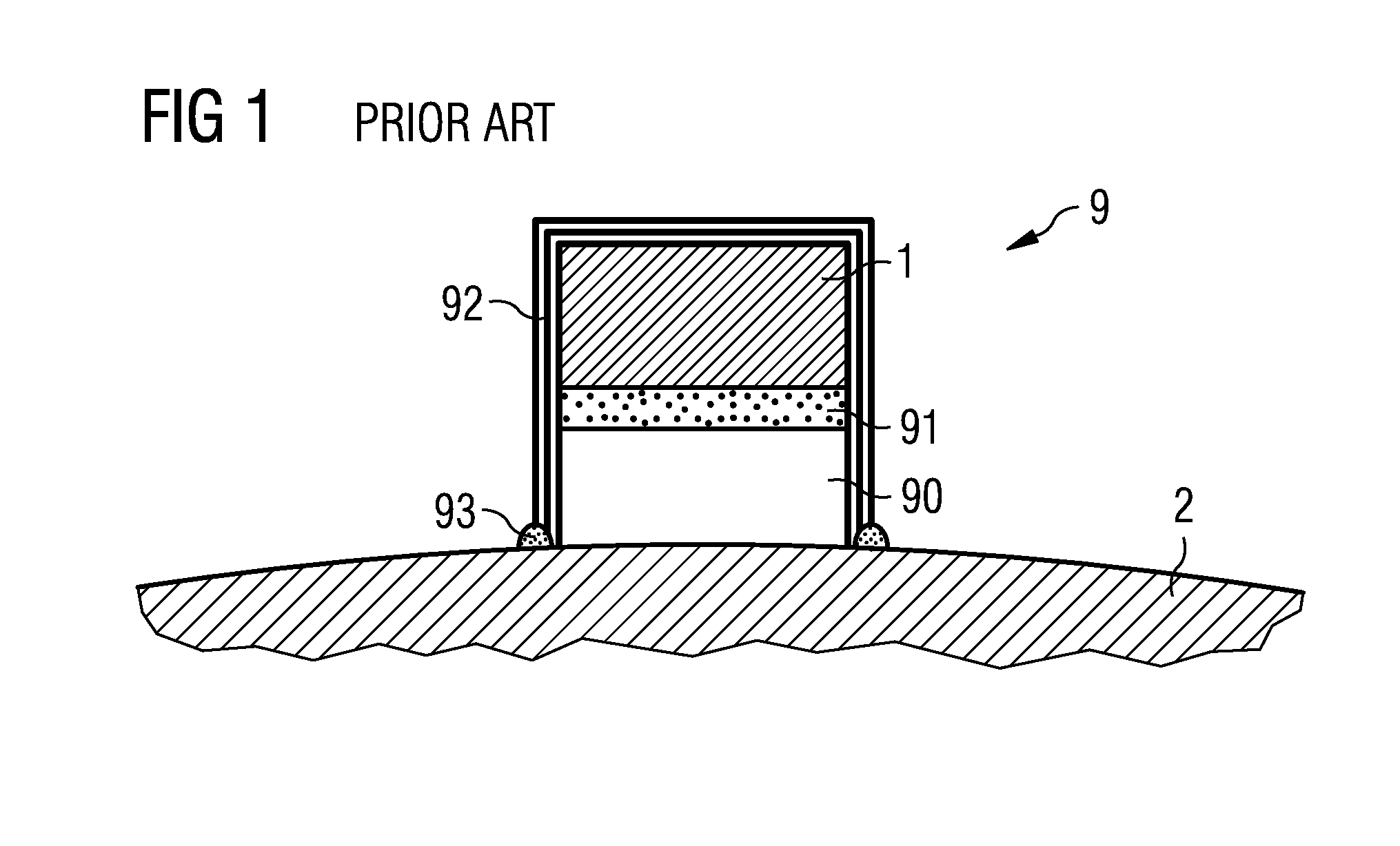
[0033]FIG. 1 shows a prior art magnet mounting arrangement 9 for a magnet 1 and a rotor 2. Many such magnets 1 may be attached to the rotor 2, but only one is shown here for the sake of clarity. The magnet 1 is shown in cross-section, and it will be understood that, for a rotor 2 with a diameter in the region of 2-6 m, such a magnet 1 can typically have a cross-sectional area in the region of 10-60 cm2. In this prior art approach, the magnet 1 is first glued to a steel base 90 by means of an adhesive layer 91. The combined base and magnet unit is then covered by a fitted steel housing 92, which in turn is soldered along its outer edges to the rotor 2.

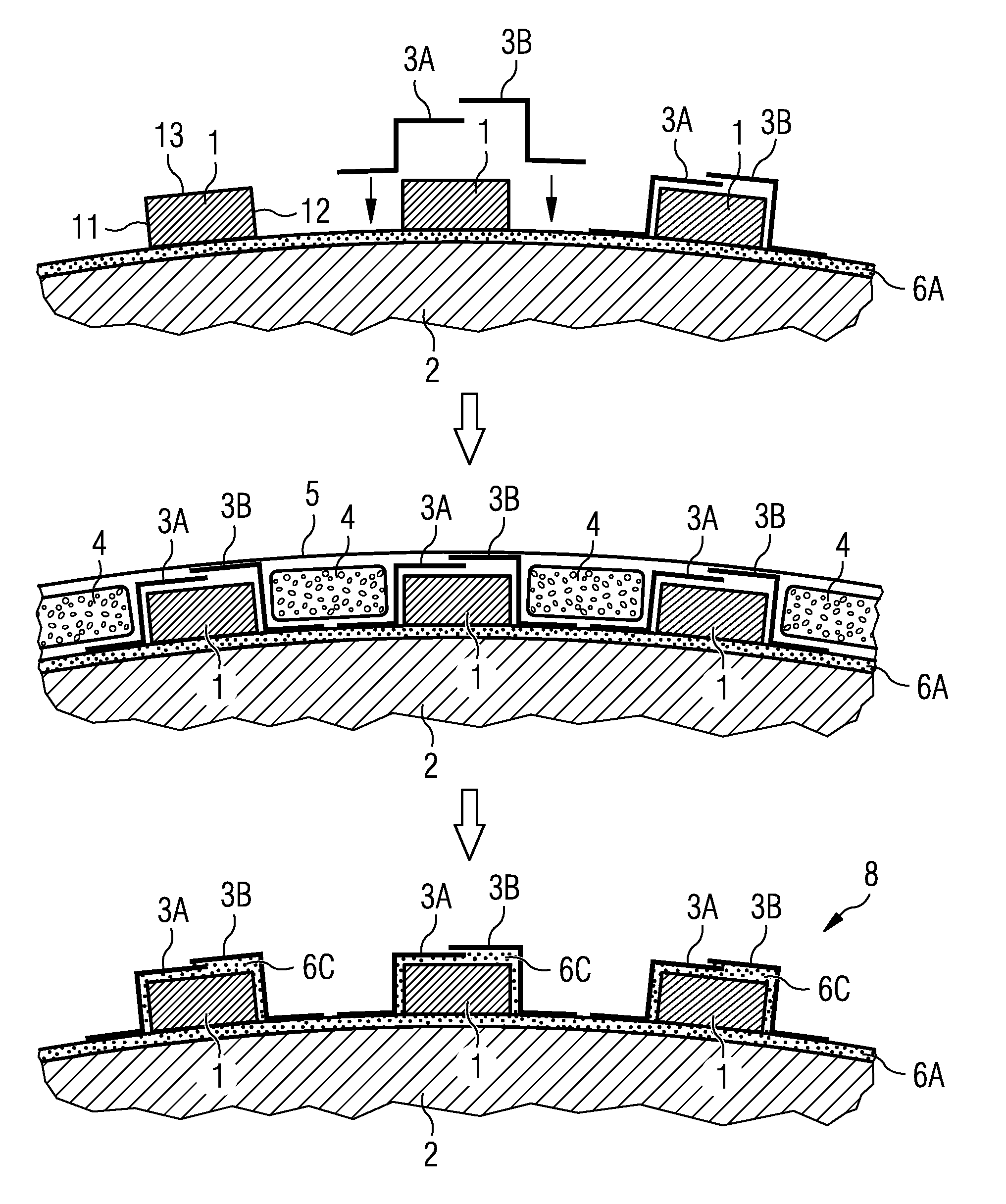
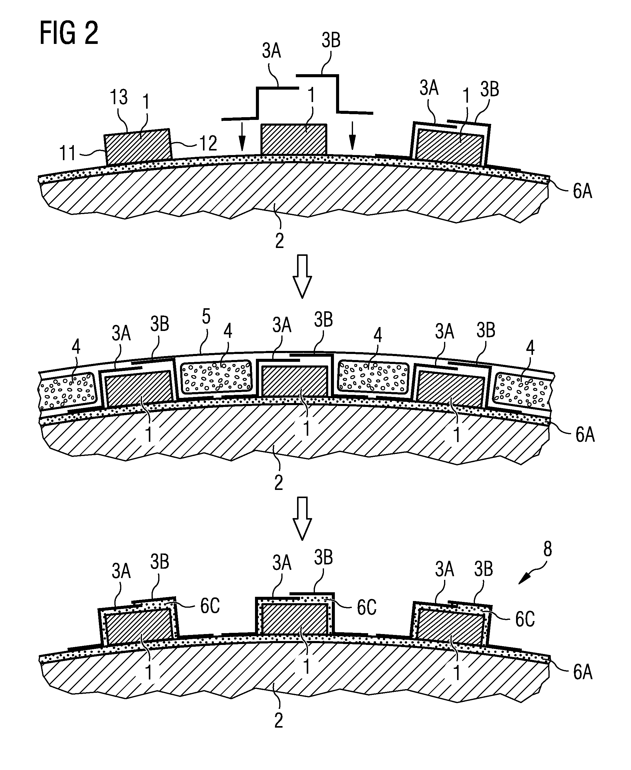
[0034]FIG. 2 illustrates steps of the inventive method of mounting a magnet 1 to a rotor 2. In a first stage, as shown in the top of the diagram, an adhesive layer 6A is applied to the surface of the rotor 2, and the magnets 1 are positioned as appropriate. Then, a pair of retainers 3A, 3B are put into place, one on each side of the mag...


PUM

PropertyMeasurementUnit
heightaaaaaaaaaa
heightaaaaaaaaaa
diameteraaaaaaaaaa

Abstract

A method of attaching a magnet to a rotor or a stator of an electrical machine is provided. The method includes arranging a magnet along a surface of the rotor or stator; arranging a pair of retainers, one on each side of the magnet; enclosing the rotor or stator, magnet and retainers in a vacuum bag; and performing vacuum evacuation to consolidate the magnet to the retainers by means of adhesive. A magnet mounting arrangement for a rotor or a stator of an electrical machine and a wind turbine with a generator including a rotor and a stator and such a magnet mounting arrangement are also provided.

Description

CROSS REFERENCE TO RELATED APPLICATIONS[0001]This application is the U.S. National Stage of International Application No. PCT / EP2010 / 059399, filed Jul. 1, 2010 and claims the benefit thereof. The International Application claims the benefits of European Patent Office application No. 10155292.5 EP filed Mar. 3, 2010. All of the applications are incorporated by reference herein in their entirety.FIELD OF INVENTION[0002]The invention describes a method of attaching a magnet to a rotor or a stator of an electrical machine. The invention further describes a magnet mounting arrangement, a generator, and a wind turbine.BACKGROUND OF INVENTION[0003]An electrical machine such as a generator can have a large field (usually the rotor), to which a corresponding large number of permanent magnets or poles is attached. During manufacture, each magnet must be firmly attached to the rotor so that it cannot come loose during operation. For a rotor with a diameter in the range of 2-6 m, a magnet can t...

Claims


Application Information

Patent Timeline
Patent Type & Authority Patents(United States)
IPC IPC(8): H02K1/27H02K15/03
CPCH02K1/278H02K15/03Y02E10/725Y02E10/72H02K1/274H02K1/28
Inventor STIESDAL, HENRIK
Owner SIEMENS AG
Why Eureka
Try Eureka