
Oscillator and self-calibration method thereof

a self-calibration and oscillator technology, applied in the field of integrated circuits, can solve the problems of large layout area, large power consumption, drawbacks of crystal oscillators, etc., and achieve the effect of accurate and stable output, accurate and stable frequency of output oscillation signals

Active Publication Date: 2015-06-30
SHANGHAI HUAHONG GRACE SEMICON MFG CORP
View PDF13 Cites 0 Cited by
  • Summary
  • Abstract
  • Description
  • Claims
  • Application Information

AI Technical Summary

Benefits of technology

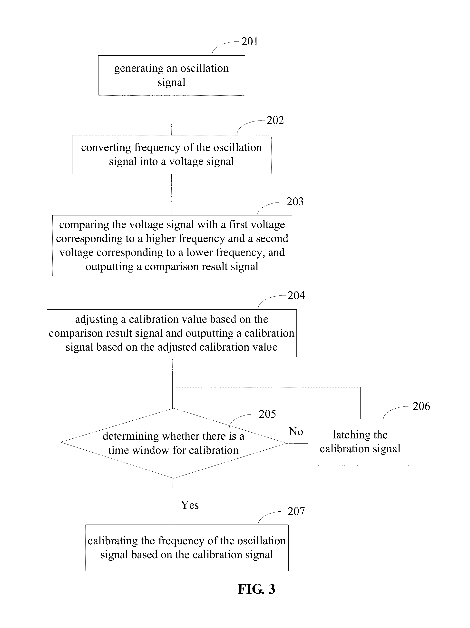
The present patent provides an oscillator that can automatically calibrate its frequency through a self-calibration process. This process involves comparing the frequency of the oscillator with a higher and a lower frequency, and adjusting the calibration value accordingly. The calibration unit then calibrates the oscillator's frequency based on the adjusted calibration value. This process ensures that the frequency of the oscillator remains accurate and stable, and can be performed periodically to achieve optimal performance. Overall, the present patent provides an improved solution for situations where accurate and stable frequency variations are critical.

Problems solved by technology

Ring oscillators have a wide range of oscillation frequency and relatively high stability, but have less resistance to power supply noises and may occupy relatively large layout areas.
However, crystal oscillators have drawbacks like larger power consumption, higher price.
Besides, it is difficult for a crystal oscillator to be integrated in a chip.
For example, due to the limitations of semiconductor manufacturing, oscillators formed at different positions of a same wafer may have disparity in oscillation frequencies.

Method used


Image

  • Oscillator and self-calibration method thereof
  • Oscillator and self-calibration method thereof
  • Oscillator and self-calibration method thereof

Examples


Embodiment Construction

[0023]Signal frequencies outputted from conventional oscillators are likely to change with work voltages, environmental temperatures and manufacturing processes, and thus are unstable. Therefore, calibrations for oscillation frequencies are required to obtain stable output frequencies.

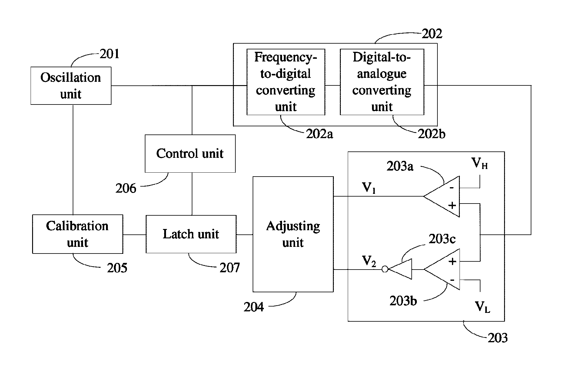
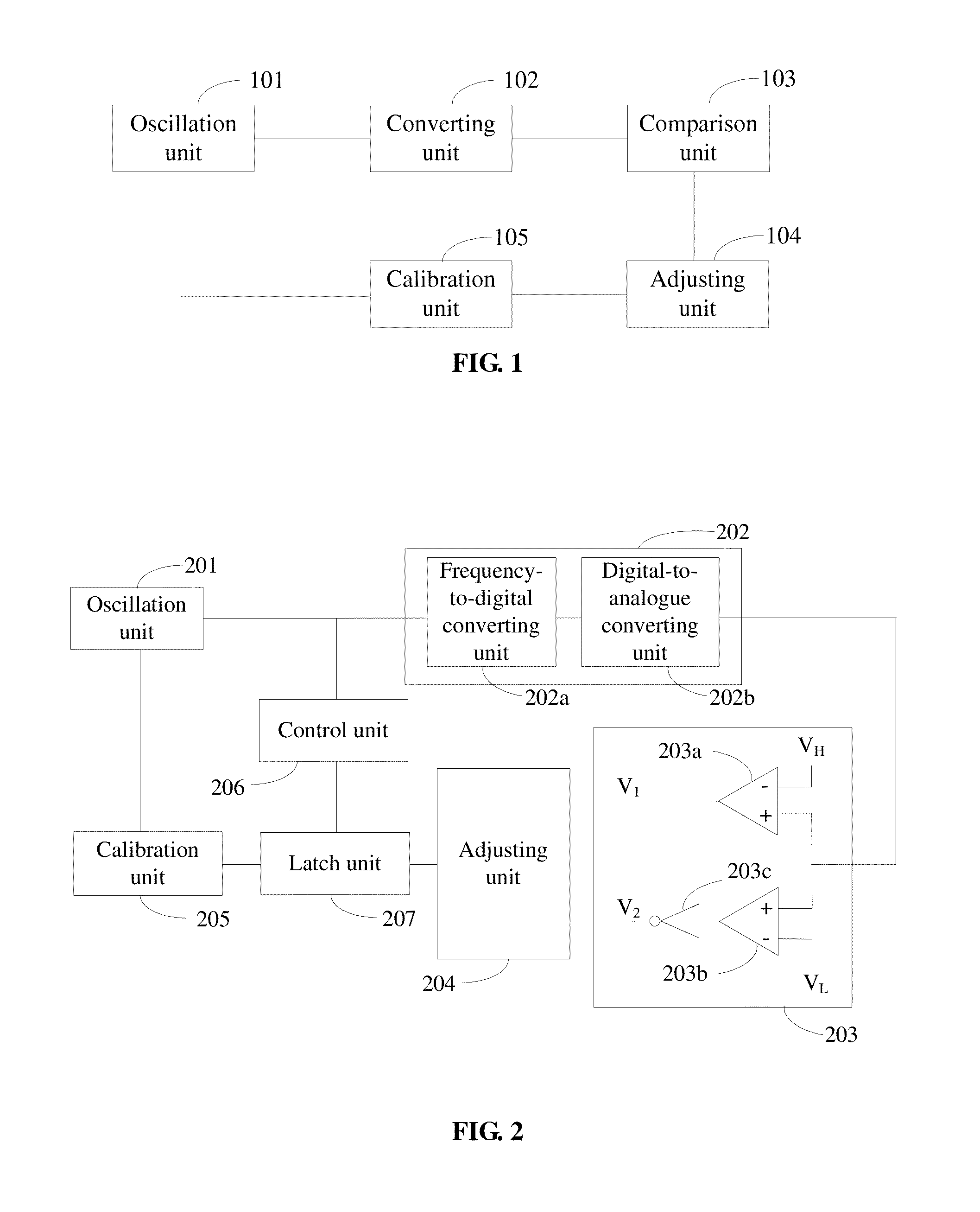
[0024]Referring to FIG. 1, an oscillator is provided according to one embodiment of the present disclosure. The oscillator may include: an oscillation unit 101 for generating an oscillation signal; a converting unit 102 for converting the oscillation signal into a voltage signal based on a frequency of the oscillation signal; a comparison unit 103 for comparing the voltage signal with a first voltage corresponding to a higher frequency and a second voltage corresponding to a lower frequency, and outputting a comparison result signal; an adjusting unit 104 for storing a calibration value, adjusting the calibration value based on the comparison result signal, and outputting a calibration signal correspon...


PUM


Abstract

An oscillator and a self-calibration method thereof are provided. The oscillator includes: an oscillation unit for generating an oscillation signal; a converting unit for converting frequency of the oscillation signal into a voltage signal; a comparison unit for comparing the voltage signal with a first voltage corresponding to a higher frequency and a second voltage corresponding to a lower frequency, and outputting a comparison result signal; an adjusting unit for storing a calibration value, adjusting the calibration value based on the comparison result signal and outputting a calibration signal corresponding to the adjusted calibration value; and a calibration unit for calibrating the frequency of the oscillation signal based on the calibration signal. Self-calibration for the frequency of the oscillation signal may be achieved, which may ensure the stability of the frequency of the oscillation signal.

Description

CROSS REFERENCE TO RELATED APPLICATIONS[0001]The present application claims priority to Chinese Patent Application No. 201210559559.9, filed on Dec. 20, 2012 and entitled “OSCILLATOR AND SELF-CALIBRATION METHOD THEREOF”, the entire disclosure of which is incorporated herein by reference.FIELD OF THE DISCLOSURE[0002]The present disclosure generally relates to the field of integrated circuit, and more particularly, to an oscillator and a self-calibration method thereof.BACKGROUND OF THE DISCLOSURE[0003]Clock signals are essential elements in large-scale digital integrated circuits. In these digital systematic circuits, normally there are three kinds of clock signal generation circuits: RC (resistance-capacitance) oscillators, ring oscillators and crystal oscillators. Ring oscillators have a wide range of oscillation frequency and relatively high stability, but have less resistance to power supply noises and may occupy relatively large layout areas. Crystal oscillators have an accurate...

Claims


Application Information

Patent Timeline
Patent Type & Authority Patents(United States)
IPC IPC(8): H03L7/093H03L7/16
CPCH03L7/16H03L7/093H03L1/00H03L7/00
Inventor CHEN, ADAYU, EMIR
Owner SHANGHAI HUAHONG GRACE SEMICON MFG CORP
Learn More