Adjustable clamp systems and methods

a clamp system and adjustable technology, applied in the field of therapeutic systems and methods, can solve problems such as the desire of doctors to pursue an inferior approach

Active Publication Date: 2015-07-07
ESTECH ENDOSCOPIC TECH +1
View PDF24 Cites 7 Cited by
  • Summary
  • Abstract
  • Description
  • Claims
  • Application Information

AI Technical Summary

Benefits of technology

[0007]An electrode assembly in accordance with embodiments of the present invention includes an electrode that is connected to at least two power supply lines. An electrode assembly (or a plurality of electrode assemblies) may be used in electrophysiology devices including, but not limited to, catheters, surgical probes and clamps. In one exemplary bipolar clamp implementation, an electrode assembly is provided on one clamp member and a similar electrode assembly (e.g. with an electrode and a pair of power return lines) is provided on the other clamp member. In some cases, an electrode assembly may include a single power return line. Such a clamp may be used to form long, continuous lesions without the gaps that may sometimes occur when a plurality of spaced power transmitting electrodes are positioned opposite a plurality of spaced return electrodes. The individual clamp members may include rotatable jawbone members that can be adjusted to be set or fixed at desired angular degrees about their longitudinal axis, thereby enabling a surgeon to create lesion lines in any of a variety of three dimensional configurations.
[0010]Often, the jaw clamps will squeeze together two layers of tissue. When the tissue layers are pressed sufficiently tightly against one another, there may be no blood between the layers. One jaw clamp can include an active (−) electrode, and the opposing jaw clamp can include a ground / return (+) electrode. Application of energy through the electrodes operates to heat the tissue, thereby forming a lesion. Embodiments of the present invention provide convenient and efficient mechanisms to change the orientation of the jaw clamps throughout various degrees or rotation. This flexibility allows the surgeon to use a single clamp design to easily access or approach the patient anatomy from different directions. For example, the surgeon may choose to treat cardiac tissue using an inferior approach or using a superior approach. In some cases, the path through which the device is maneuvered may depend on the size of the patient. For example, a physician may elect a superior approach with a larger patient. In some cases, the path through which the device is maneuvered may depend on the patient's anatomy. For example, when approaching the heart, the physician may wish to pursue an inferior approach due to the location of branching great vessels and the conical shape of the rib cage. In some cases, the path through which the device is maneuvered may depend on the location of an access port or incision. For example, if an incision is made slightly high relative to the heart, the physician may chose a superior approach.

Problems solved by technology

For example, when approaching the heart, the physician may wish to pursue an inferior approach due to the location of branching great vessels and the conical shape of the rib cage.

Method used


Image

  • Adjustable clamp systems and methods
  • Adjustable clamp systems and methods
  • Adjustable clamp systems and methods

Examples


Embodiment Construction

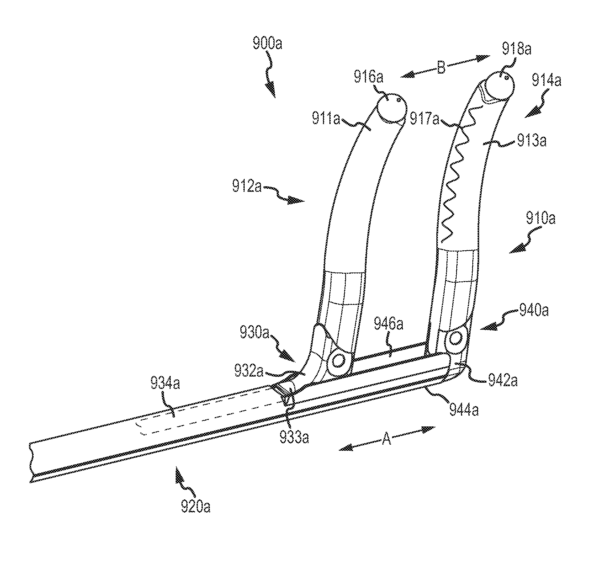
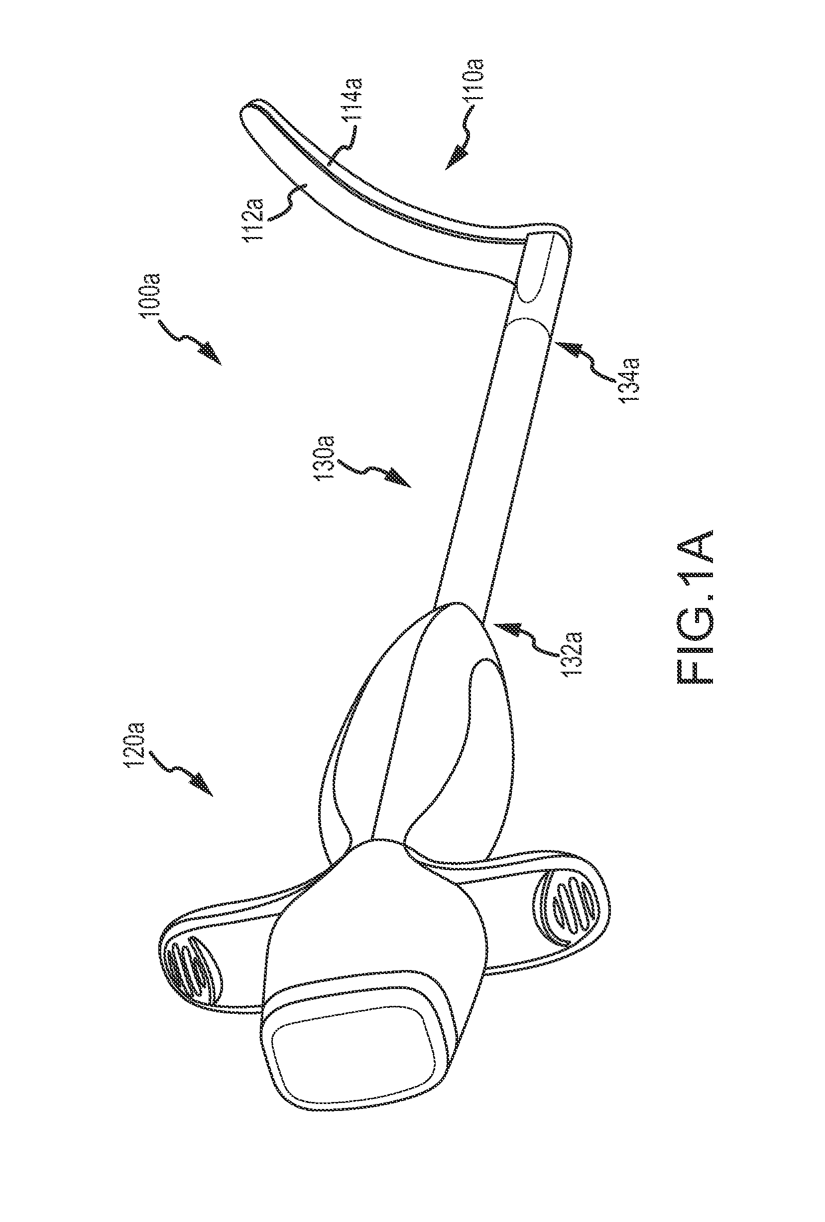
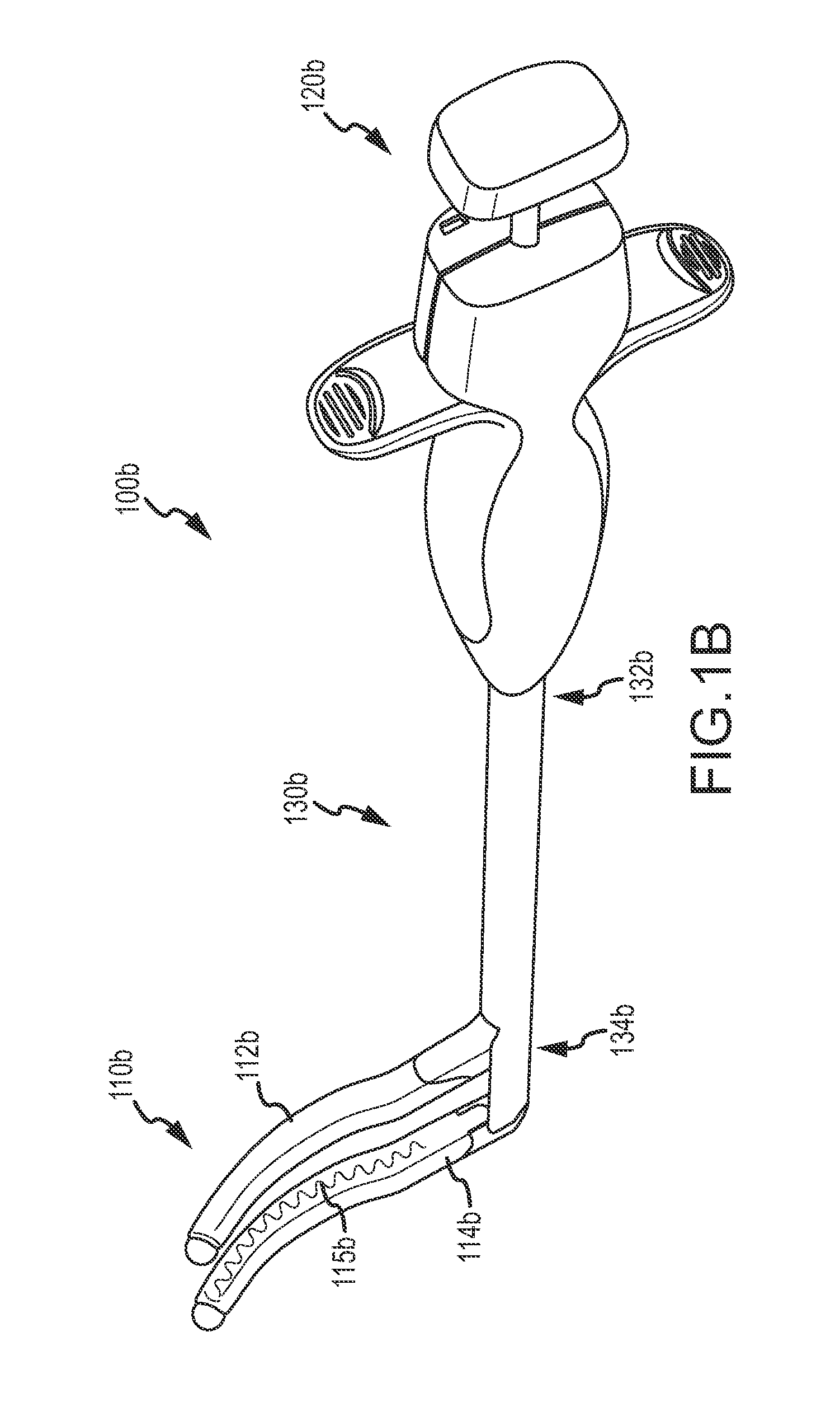
[0036]Embodiments of the present invention encompass systems and methods that involve a treatment system having a disposable dedicated bipolar clamp. In some cases, a bipolar clamp device may include cooled RF technology. Optionally, treatment devices may include a flexible serpentine plate electrode. Treatment devices may be adjustable for ease of use by the surgeon in any of a variety of configurations, including a right hand configuration, a left hand configuration, a jaws up configuration, and a jaws down configuration. The treatment device can adopt such configurations as the surgeon adjustably flips or rotates the jaws through various degrees of angular rotation. In some cases, a treatment device includes a symmetric, unified release trigger.

[0037]Turning now to the drawings, FIG. 1A illustrates aspects of a treatment system 100a according to embodiments of the present invention. Treatment system 100a includes a clamp assembly 110a, an actuator assembly 120a, and a coupling as...


PUM


Abstract

Tissue treatment systems include an actuator handle assembly coupled with a clamp assembly having a first jaw mechanism and a second jaw mechanism. A first jaw mechanism includes a first flexible boot, a first flexible ablation member coupled with the first flexible boot, and a first rotatable jawbone disposed within the first flexible boot. A second jaw mechanism comprises a second flexible boot, a second flexible ablation member coupled with the second flexible boot, and a second rotatable jawbone disposed within the second flexible boot.

Description

CROSS-REFERENCES TO RELATED APPLICATIONS[0001]This application is a nonprovisional of, and claims the benefit of the filing date of U.S. Provisional Patent Application No. 61 / 288,031 filed Dec. 18, 2009. This application is also related to U.S. Patent Application Nos. 60 / 337,070 filed Dec. 4, 2001; Ser. No. 10 / 080,374 filed Feb. 19, 2002; Ser. No. 10 / 255,025 filed Sep. 24, 2002; Ser. No. 10 / 272,446 filed Oct. 15, 2002; Ser. No. 10 / 410,618 filed Apr. 8, 2003; Ser. No. 11 / 067,535 filed Feb. 25, 2005; Ser. No. 11 / 148,611 filed Jun. 8, 2005; 61 / 051,975, filed May 9, 2008; Ser. No. 12 / 255,076 filed Oct. 21, 2008; and Ser. No. 12 / 463,760 filed May 11, 2009. The entire content of each of these filings is incorporated herein by reference for all purposes.BACKGROUND OF THE INVENTION[0002]Embodiments of the present invention relate generally to therapeutic systems and methods, and more particularly, to techniques that are well suited for the formation of lesions in body tissue.[0003]There are...

Claims


Application Information

Patent Timeline
Patent Type & Authority Patents(United States)
IPC IPC(8): A61B18/18A61B18/14A61N7/02A61B18/20A61B18/00
CPCA61B18/1442A61B18/1815A61B18/20A61B2018/00023A61B2018/00351A61B2018/00702A61B2018/00791A61B2018/145A61N7/02A61B18/0206A61B2018/0225A61B18/06A61B18/085A61B18/1206A61B2018/00273A61B2018/00577
Inventor MOREJOHN, DWIGHT P.IBRAHIM, TAMERBANCHIERI, MICHAEL J.STEPHANIAN, ARA M.
Owner ESTECH ENDOSCOPIC TECH
Why Eureka
Try Eureka