

System for electrical stimulation of nerves
a nerve and electrical stimulation technology, applied in the field of nerve electrical stimulation, can solve the problems that hemiplegic patients can be difficult to plug and unplugg connectors, and achieve the effect of improving the electrical stimulation effect of the nerv
- Summary
- Abstract
- Description
- Claims
- Application Information
AI Technical Summary
Benefits of technology
Problems solved by technology
Method used
Image

Examples
Embodiment Construction
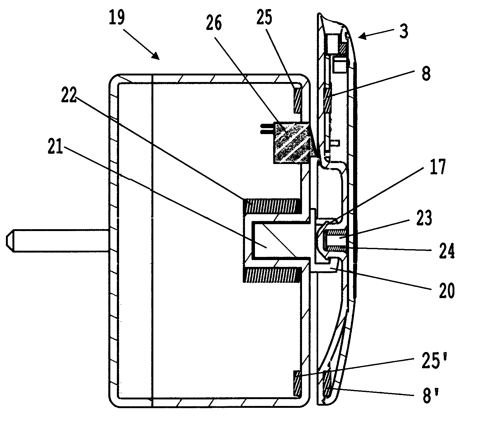
[0006]It is an object of the present invention to provide a system for stimulation of nerves, which is simpler to use by hemiplegic patients and in addition avoids the situation where charging and electrical stimulation is carried out simultaneously.
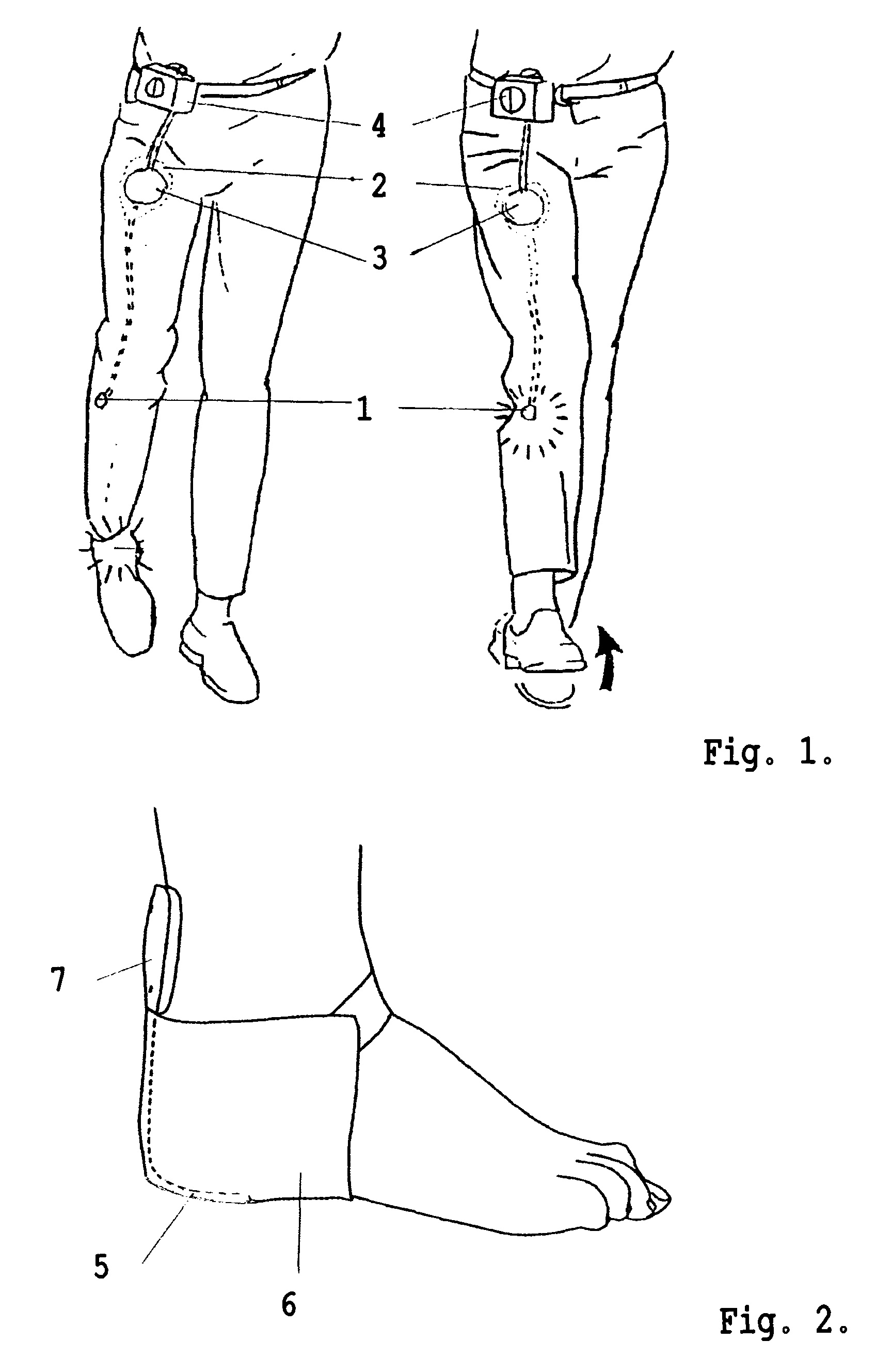
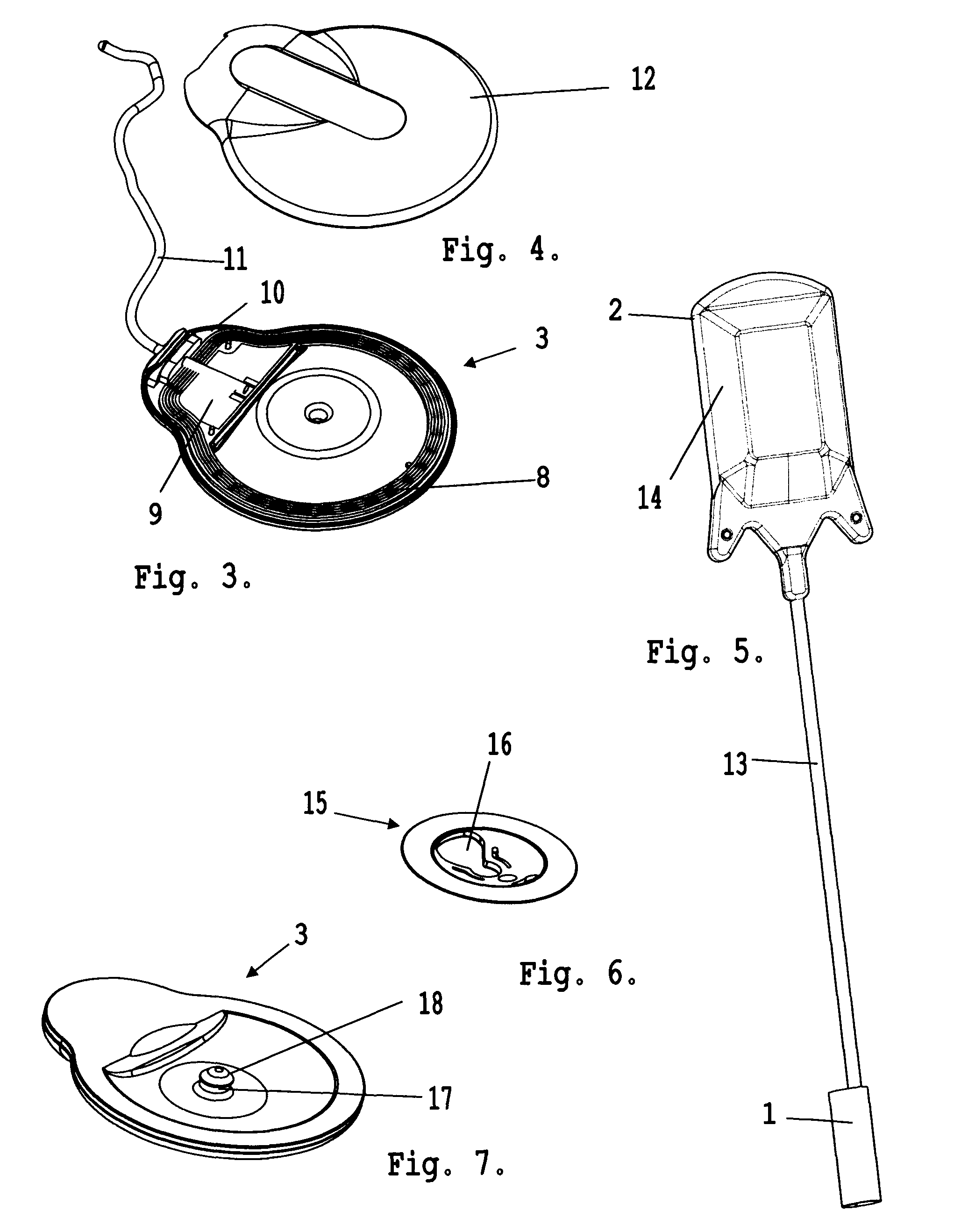
[0007]In a first aspect, the present invention provides a system for stimulation of nerves comprising at least one electrode, a pulse generator for generating a pulse pattern to be forwarded to that at least one electrode, the pulse generator further being equipped with a rechargeable battery for supplying the system with a source of electrical energy, an inductive link between the pulse generator and the electrode, comprising an antenna adapted to be mounted on the skin of the patient and a counterpart in form of an implantable antenna adapted to be implanted in the thigh of the patient and an inductive link for charging the rechargeable battery in the pulse generator comprising an antenna for acting as a counterpart for an inductive ch...
PUM
 Abstract
Description
Claims
Application Information