Rotor for a laboratory centrifuge with rotor hub cooling means

a technology of cooling means and rotors, which is applied in the direction of centrifuges, etc., can solve the problems of relatively high structural measures and achieve the effect of simple construction

Active Publication Date: 2015-07-14
SIGMA LABORZENTRIFUGEN
View PDF18 Cites 3 Cited by
  • Summary
  • Abstract
  • Description
  • Claims
  • Application Information

AI Technical Summary

Benefits of technology

[0004]In view of the preceding, the object of the invention is to design a rotor for a laboratory centrifuge with which the thermal conditions in the housing interior, the rotor, and consequently also the substance mixture to be treated can easily be made constant.
[0006]The grooves extend between the two frontal face ends of the rotor hub, which consists of an annular flange and a fastening element conformed integrally therewith. The medium is thus directed via the peripheral areas of the rotor hub, the central area thereof being ad adapted for attachment to a drive shaft. In this way, the rotor hub is not prevented from performing its intended function.
[0008]A variation of the rotor consists of a rotor body, a cap, a cap screw, a specially designed nut and the rotor hub. It is evident that the cap can be removed by loosening the cap screw without otherwise interfering with the integrity of the rotor.
[0009]The nut has two internal threads, one of which is designed for a screw connection with the cap screw, and the other for screw connection with the rotor hub or the fastening element thereof. The end face of the fastening element is retained within the nut at a distance from the end face of the part that is connected to the cap screw. This ensures that a media flow is not impeded by the radially outer grooves of the rotor hub due to the threaded connection thereof with the nut.
[0013]It may be seen from the foregoing notes that the rotor according to the invention represents as device that is notable for its simple construction and which serves as a contribution to improved and particularly consistent guidance of a medium, particularly for the uniform thermal conditioning of the rotor of a laboratory centrifuge, including the substance mixture to be treated.

Problems solved by technology

However, in order to obtain constant thermal conditions for the rotor, the interior of the centrifuge and the substance mixture to be treated, it is also necessary to implement particular structural measures, which are relatively expensive.

Method used


Image

  • Rotor for a laboratory centrifuge with rotor hub cooling means
  • Rotor for a laboratory centrifuge with rotor hub cooling means
  • Rotor for a laboratory centrifuge with rotor hub cooling means

Examples


Embodiment Construction

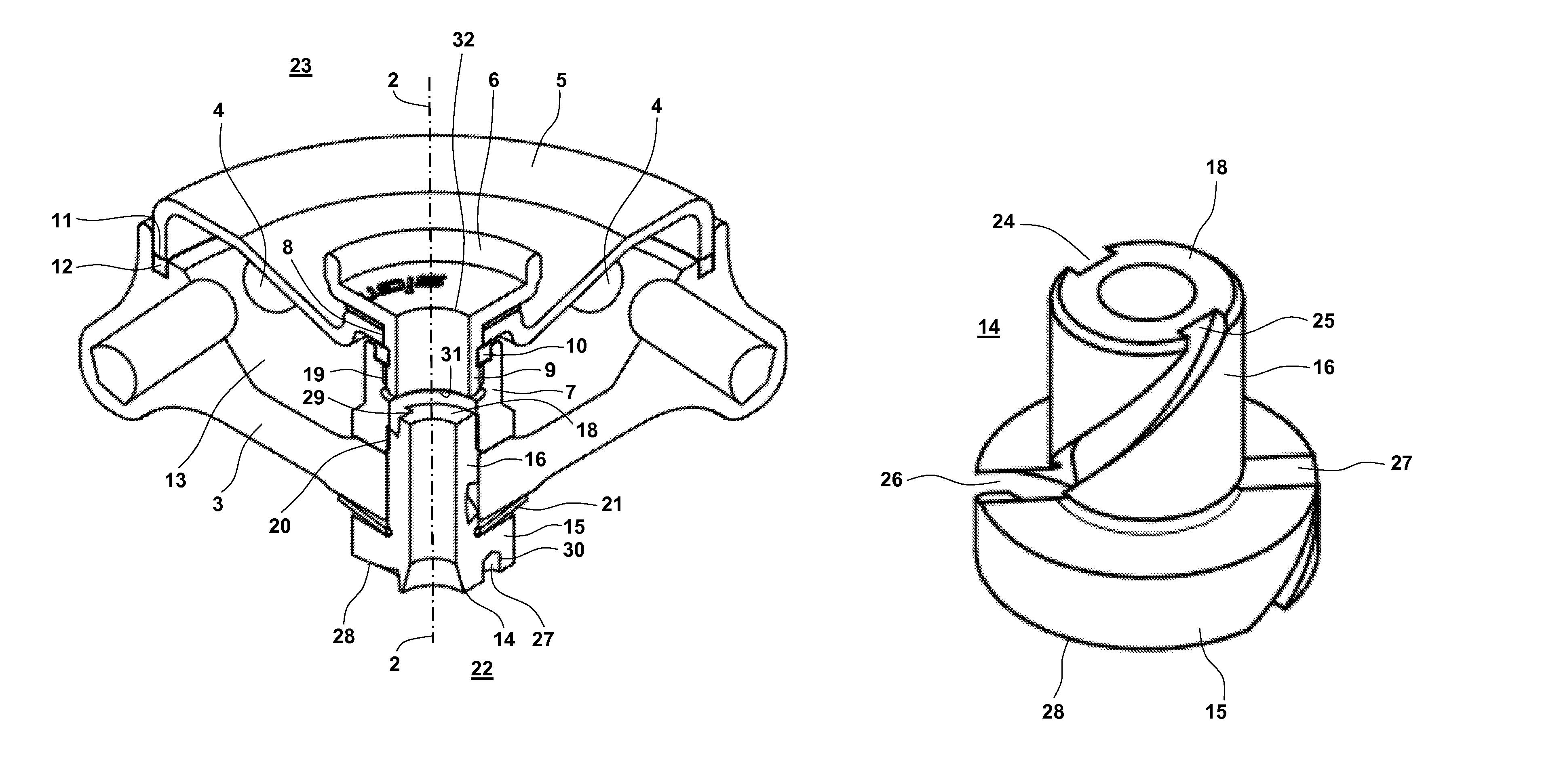
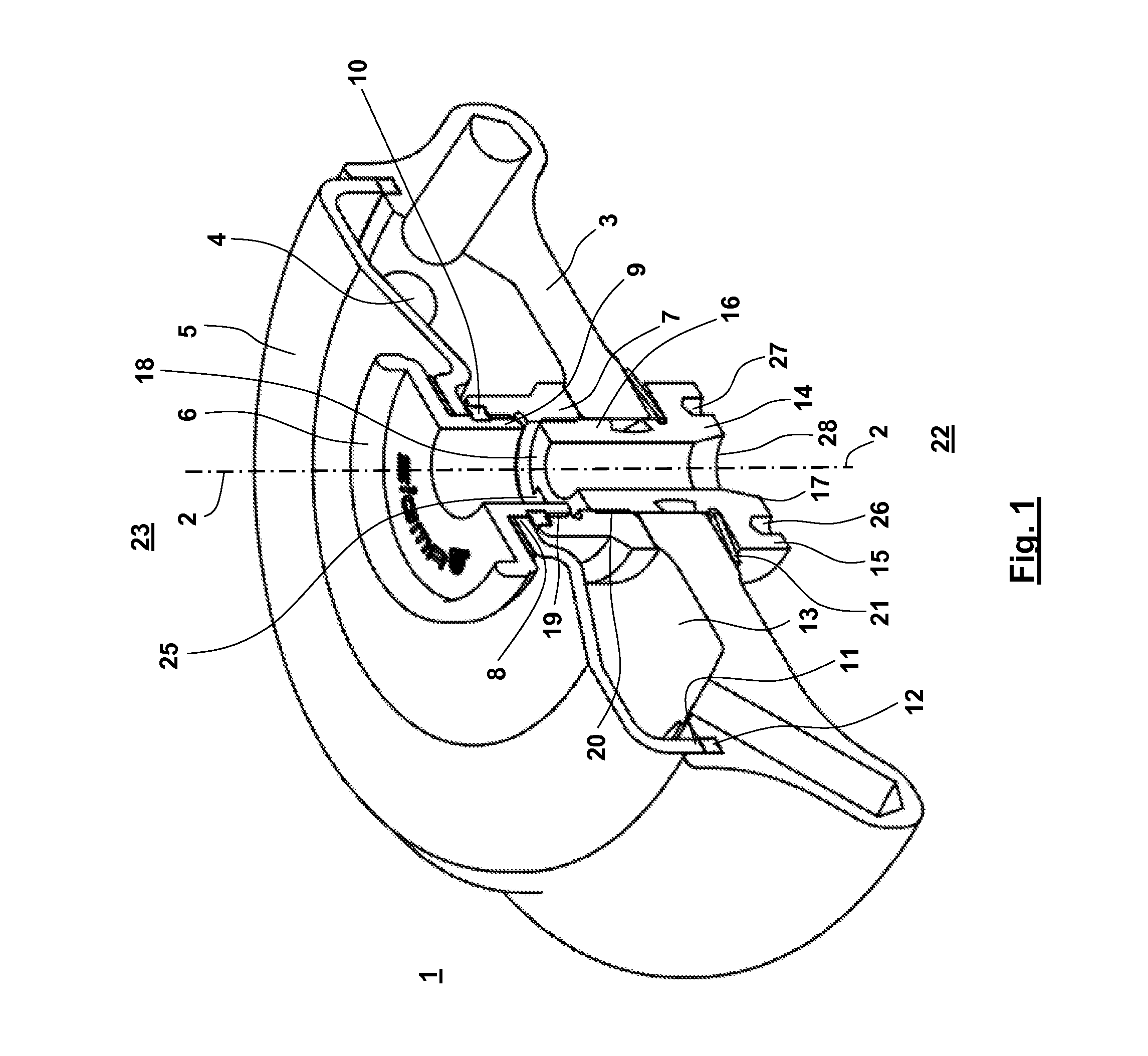
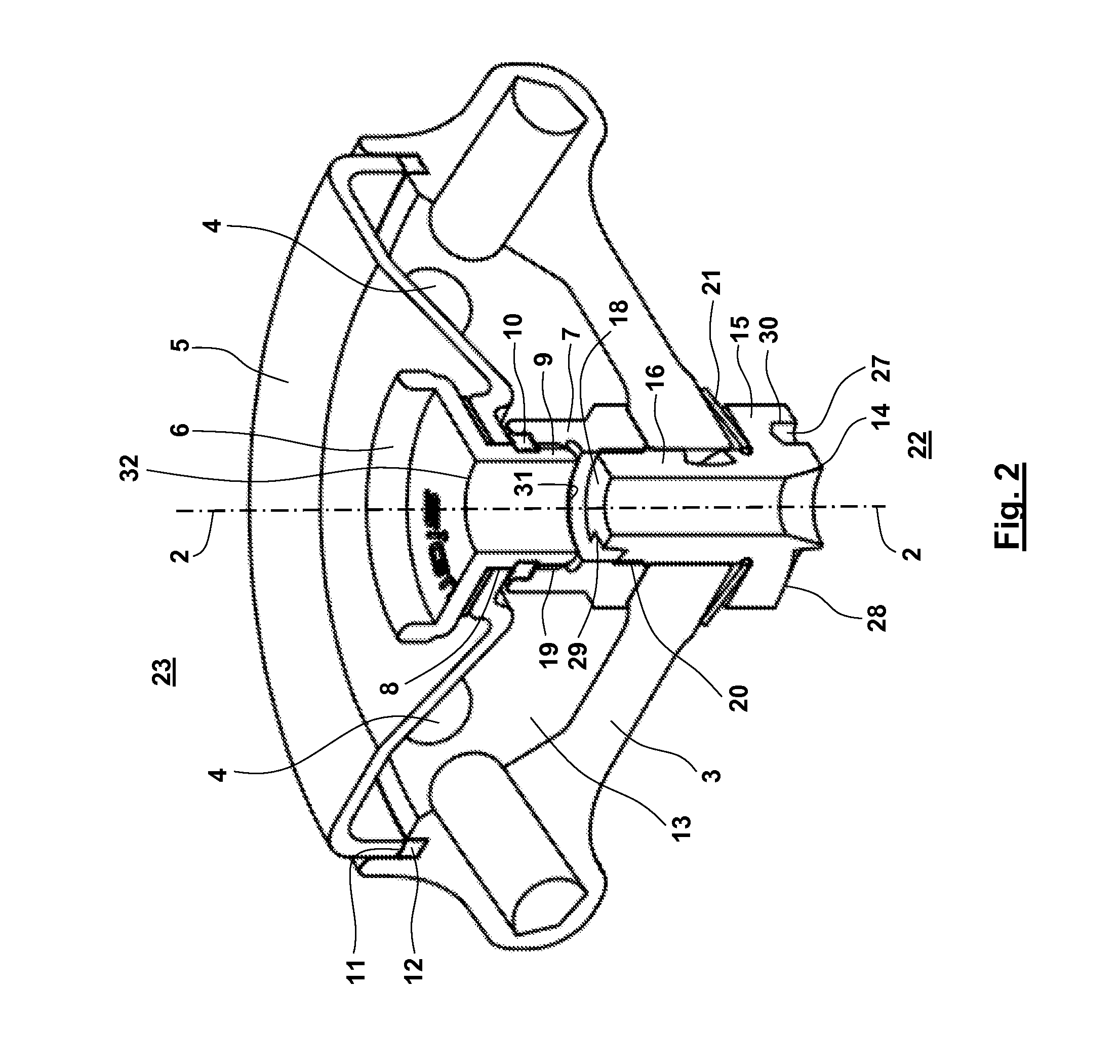
[0018]Reference sign 1 in FIGS. 1 and 2 designates a rotor of a laboratory centrifuge that is not further illustrated, which rotor is of rotationally symmetrical construction about axis 2 thereof. Said rotor consists of a rotor body 3, the peripheral region of which includes holders 4, which are intended in known manner to accommodate receptacles filled with a substance mixture intended for treatment by centrifuging.

[0019]Reference sign 5 denotes a cap that covers rotor body 3 and is screwed to a nut 7 located below cap 5 by means of a cap screw 6 that is aligned coaxially with axis 2. A hollow cylindrical element 9 with an external thread extending through a cutout 8 in cap 5 and abutting with cap screw 6 engages with an internal thread 19 of nut 7. A sealing ring 10, preferably in the form of a four-lip seal, is positioned between cap 5 and nut 7, accommodated in annular recesses that are located radially opposite one another.

[0020]The rim of cover 5 has a bowl-like shape with an ...


PUM


Abstract

A rotor body (3) for a laboratory centrifuge includes a rotor hub (14) which is inserted in a central opening and on the outside of which, at least one helically curve continuous groove (27) runs so as to form a transport facility for cooling air. The cooling air is effective in the direction of the axis (2) of the rotor hub (14) between the upper side (23) and the underside (22) of the rotor (1). In this manner, a cooling airstream which runs axially through the rotor (1) and undergoes direct thermal exchange with the rotor (1) and the mixtures to be treated in the laboratory centrifuge can be realized. No additional installation volume is required for this measure and equalization of the temperature of the rotor and the housing accommodating the rotor can be achieved.

Description

[0001]The instant application should be granted the priority dates of Aug. 24, 2012, the filing date of the corresponding German patent application DE 20 2012 008 062.8, as well as Jul. 24, 2013, the filing date of the international patent application PCT / EP2013 / 002188.[0002]The invention relates to the rotor of a laboratory centrifuge.BACKGROUND OF THE INVENTION[0003]Laboratory centrifuges consist of a housing that is closable with a cap, in which a rotor connected to an electric drive unit is suspended in such manner that it is able to oscillate. The peripheral region of the rotor is furnished with a series of holders, into which receptacles intended as containers for a substance mixture that is to be centrifuged may be placed. The rotor is further equipped with a rotor hub, by means of which it may be fitted onto a drive shaft inside the housing. Centrifuging must often be carried out under certain thermal conditions, taking into account the chemico-physical properties of the sub...

Claims


Application Information

Patent Timeline
Patent Type & Authority Patents(United States)
IPC IPC(8): B04B15/02B04B7/08B04B5/04B04B7/02B04B9/08
CPCB04B15/02B04B5/0414B04B7/02B04B7/08B04B2007/025B04B2009/085
Inventor TODTEBERG, ECKHARDBITTNER, MATTHIAS
Owner SIGMA LABORZENTRIFUGEN
Why Eureka
Try Eureka