Eureka AIR delivers breakthrough ideas for toughest innovation challenges, trusted by R&D personnel around the world.

Cap handling tool and method of use

a technology of handling tool and cap, which is applied in the field of cap handling tool and method of use, can solve the problems of repetitive movements, tedious and time-consuming, and sprinkling of some contents from the cap, and achieve the effect of preventing the contamination of the cap

Active Publication Date: 2015-07-14
NEOGEN FOOD SAFETY US HOLDCO CORP
View PDF16 Cites 16 Cited by
  • Summary
  • Abstract
  • Description
  • Claims
  • Application Information

AI Technical Summary

Benefits of technology

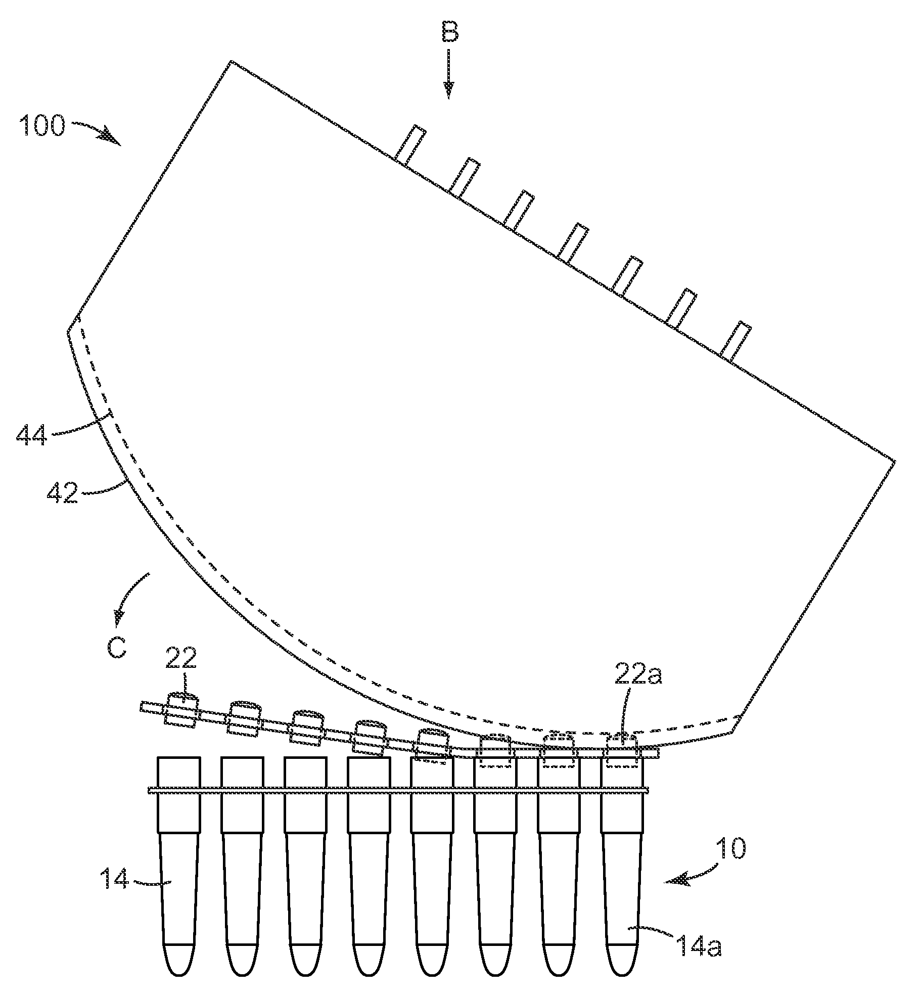
The present disclosure is related to a tool and methods for removing a plurality of caps from two or more containers, such as microcentrifuge tubes used for polymerase chain reaction. The tool can also be used to restore the caps on the containers. The tool is designed to hold the caps temporarily, allowing the operator to use both hands for other tasks, while preventing contamination of the caps with materials present on the surface. The tool can be used on tubes containing two, three, four, six, or eight caps, and can be temporarily placed on a surface for other tasks. In summary, the tool provides a convenient and safe way to remove and replace caps on containers, particularly in chemical or biochemical reactions.

Problems solved by technology

Furthermore, recapping the tubes also might result in spillage of some of the contents from the tubes.
To minimize spillage, the technician will typically need to carefully remove and / or replace one cap at a time, which is not only tedious and time consuming, but also requires repetitive movements.
Moreover, practice has shown that the closely packed tubes in the tube rack are difficult to recap manually.
A careless or hurried technician may not always get all of the tubes properly recapped, which may result in test failures due to evaporation or contamination.
Removing strips of caps by hand also can result in stretching of the strip, making recapping subject to failure.

Method used


Image

  • Cap handling tool and method of use
  • Cap handling tool and method of use
  • Cap handling tool and method of use

Examples


embodiments

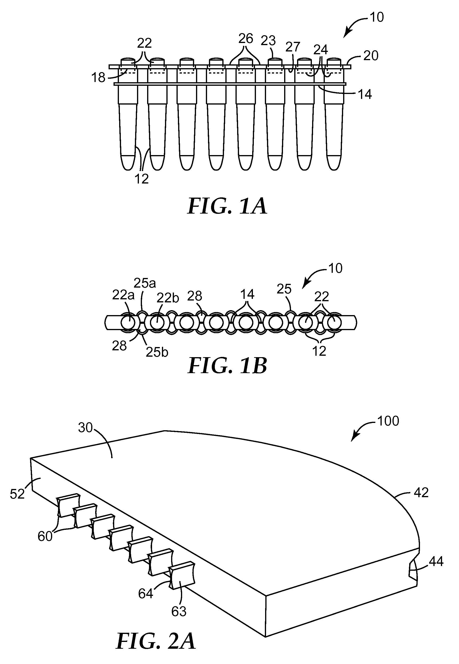
[0045]Embodiment 1 is a tool for use in uncapping a plurality of linearly-oriented, spaced-apart tubes; the tubes capped with a unitary closure device comprising a plurality of spaced-apart, linearly-oriented alternating caps and openings, each cap having a cap upper surface and being connected to at least one adjacent cap by at least two connecting structures, each of the at least two connecting structures having a connecting structure upper surface and a connecting structure lower surface, the at least two connecting structures and two adjacent caps forming a boundary of an opening; the tool comprising:

[0046]a body having first portion for engagement by a user and a second portion comprising a base and a plurality of spaced-apart projections extending therefrom;

[0047]wherein each projection comprises a longitude and a terminus;

[0048]wherein each projection is configured for releasably engaging one of the openings in the unitary closure device;

[0049]wherein the plurality of project...


PUM


Abstract

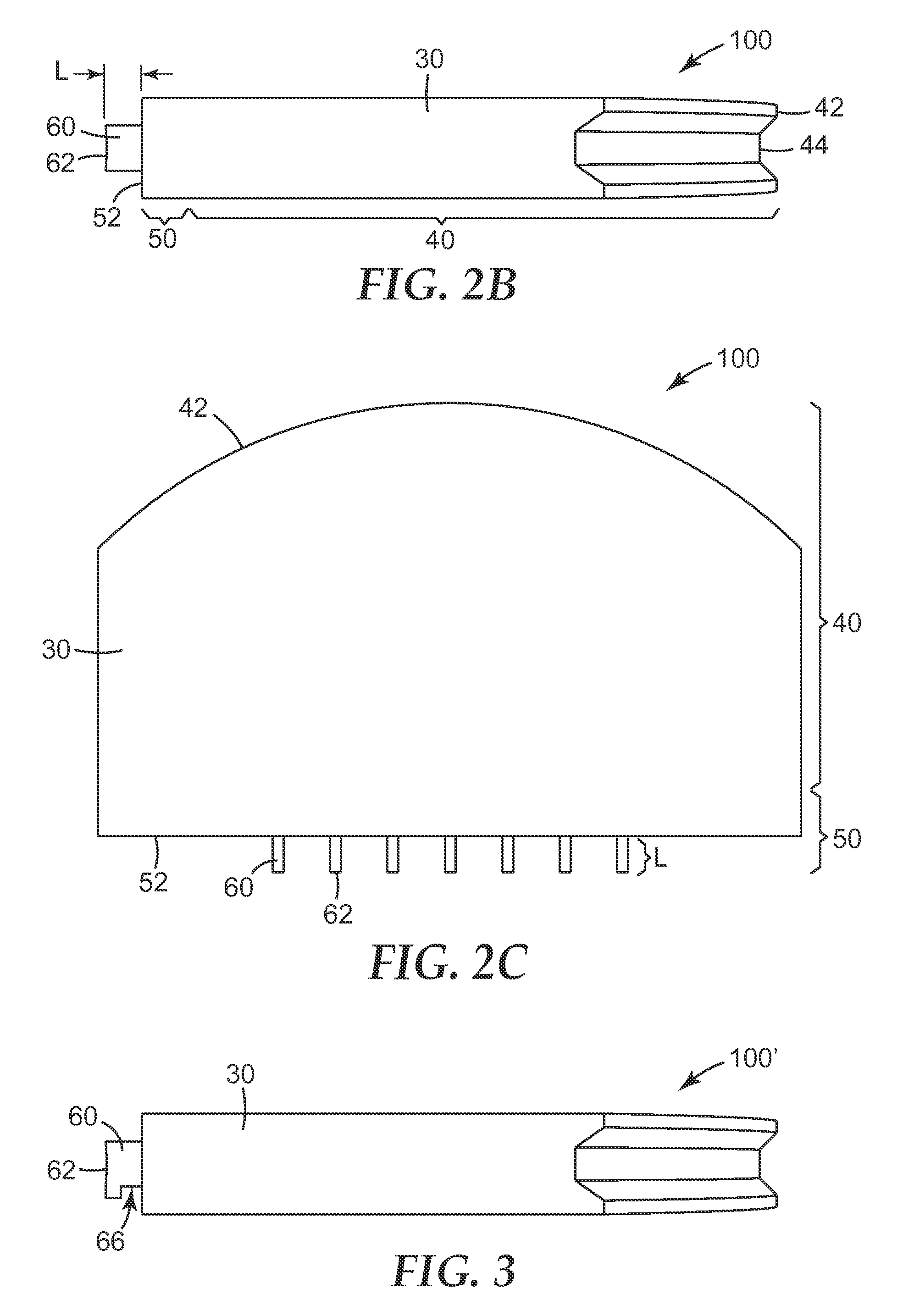
A tool (100) is provided for use in uncapping a plurality of linearly-oriented, spaced-apart tubes; the tubes capped with a unitary closure device comprising a plurality of spaced-apart, linearly-oriented alternating caps and openings, each cap having a cap upper surface and being connected to at least one adjacent cap by at least two connecting structures, each of the at least two connecting structures having a connecting structure upper surface and a connecting structure lower surface, the at least two connecting structures and two adjacent caps forming a boundary of an opening. The tool comprises a body (30) having first portion (42) for engagement by a user and a second portion comprising a base (52) and a plurality of spaced-apart projections (60) extending there-from. Each projection is configured for releasably engaging one of the openings in the unitary closure device. Optionally, the first portion is configured in a non-coplanar relationship with respect to the second portion. Methods of use are also provided.

Description

CROSS REFERENCE TO RELATED APPLICATION[0001]This application is a national stage filing under 35 U.S.C. 371 of PCT / US2012 / 049239, filed Aug. 2, 2012, which claims the benefit of U.S. Provisional Patent Application No. 61 / 514,298, filed Aug. 2, 2011, which is incorporated herein by reference in its entirety.BACKGROUND[0002]High-throughput biochemical assays often use of unitary strips of 8 reaction tubes, which ordinarily are loaded into wells in a tube rack for processing. In some apparatus, four such tube racks are processed simultaneously. In use, the operator loads a strip of capped tubes into the tube rack and removes the strip of caps manually by pulling on the tab to lift the caps progressively from the tubes at one end to the other. The tubes are then loaded with the appropriate reagents, usually with a micropipette, and recapped by hand. The procedure of uncapping and recapping is repeated after the process (e.g., DNA amplification) to remove the samples for analysis.[0003]I...

Claims


Application Information

Patent Timeline
Patent Type & Authority Patents(United States)
IPC IPC(8): B67B7/02B67B7/00B01L99/00B01L3/00
CPCB67B7/02B01L99/00B67B7/00B01L3/50853B01L3/50855B01L2200/0689
Inventor BJORK, JASON W.
Owner NEOGEN FOOD SAFETY US HOLDCO CORP
Why Eureka
Eureka Blog
Learn More