Bulb-shaped lamp and lighting device

Active Publication Date: 2015-07-14
PANASONIC CORP
View PDF33 Cites 1 Cited by
  • Summary
  • Abstract
  • Description
  • Claims
  • Application Information

AI Technical Summary

Benefits of technology

[0022]With the above structure, the air space exists between the circuit holder member and the heat sink, and/or between the circuit holder member and the heat conduction member, with the result that the lighting circuit is isolated from the air space by the circuit holder member. This reduces the amount of heat conducted from the heat sink to the lighting circuit, and lightens thermal load on the electronic components of the lighting circuit.
[0023]Because the air space exists between the circuit holder member and the heat sink, and/or between the circuit holder member and the heat conduction member, the heat generated in the light emitting module and the lighting circuit is not easily stored inside the light emitting module and the lighting circuit.
[0024]With the above structure, the fraction S1/S2 satisfies the relationship 0.5≦S1/S2, where S1 denotes an area of a portion of the heat conduction member that is in contact with the heat sink, and S2 denotes an area of a portion of the heat conduction member that is in contact with the substrate of th

Problems solved by technology

However, the problem with conventional lighting devices using LEDs as light sources, such as the above-described LED light bulb, is that it is difficult to simultaneously achieve (i) improvement in the heat dissipation properties

Method used


Image

  • Bulb-shaped lamp and lighting device
  • Bulb-shaped lamp and lighting device
  • Bulb-shaped lamp and lighting device

Examples


first embodiment

[First Embodiment]

1. Structure

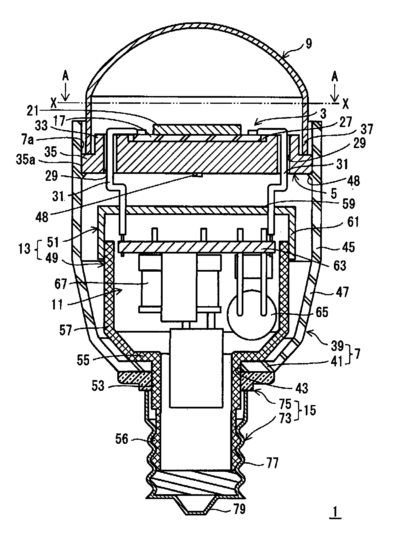
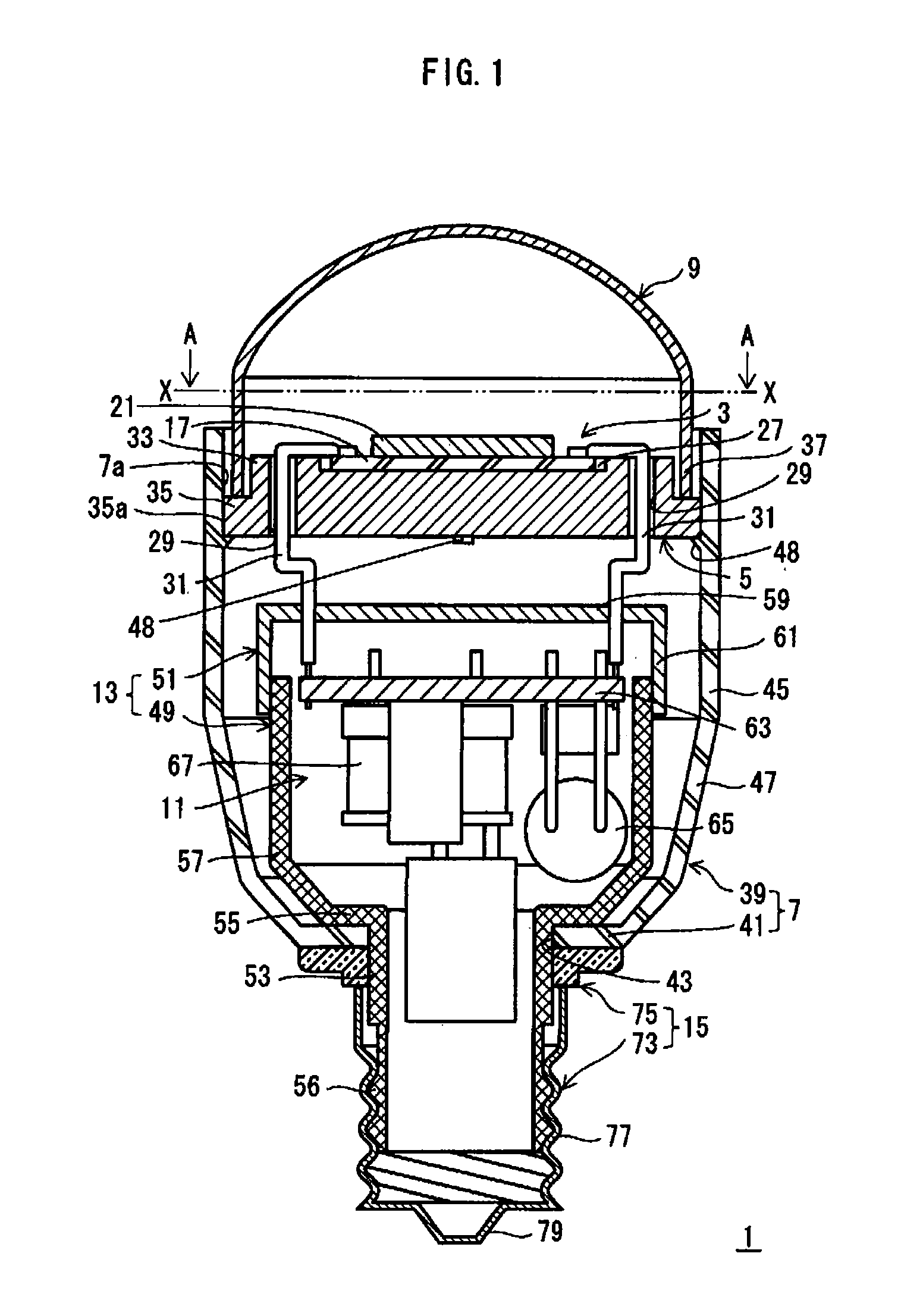
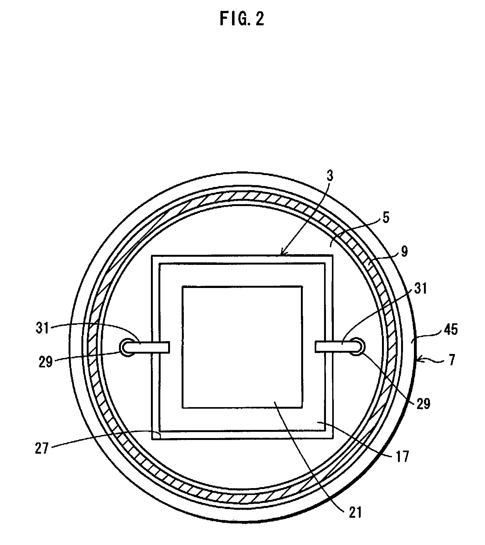
[0075]FIG. 1 is a longitudinal cross-sectional view of a bulb-type lamp pertaining to First Embodiment of the present invention. FIG. 2 shows a cross section taken along a line X-X of FIG. 1 when viewed in a direction of arrows A.

[0076]As shown in FIG. 1, a bulb-type lamp (hereinafter referred to as an “LED light bulb”) 1 is composed of (i) an LED module 3 comprising a plurality of LEDs 19 as a light source, (ii) a mount member 5 on which the LED module 3 has been mounted, (iii) a case 7, to a first end portion thereof the mount member 5 is attached, (iv) a globe 9 that covers the LED module 3, (v) a lighting circuit 11 that lights the LEDs (19) (causes the LEDs (19) to emit light), (vi) a circuit holder 13 positioned inside the case 7, with the lighting circuit 11 disposed inside the circuit holder 13, and (vii) a base member 15 attached to a second end portion of the case 7. The LEDs 19, the LED module 3, the mount member 5, the case 7, the lighting c...

second embodiment

[Second Embodiment]

[0145]In First Embodiment, the heat generated in the LED module 3 is conducted from the mount member 5 to the case 7. The most part of the heat conducted to the case 7 is dissipated to the open air. Part of the heat transferred to the case 7 is conducted to and stored in the air inside the case 7.

[0146]An LED light bulb pertaining to Second Embodiment is structured such that the heat conducted from an LED module to the air inside a case via the case is ultimately dissipated to the open air by linking the air inside the case to the outside of the case.

[0147]FIG. 8 shows an external appearance of the LED light bulb pertaining to Second Embodiment of the present invention.

[0148]A case and a circuit holder provided in an LED light bulb 101 pertaining to Second Embodiment are different in structure from the case and the circuit holder provided in the LED light bulb 1 pertaining to First Embodiment. Other parts in the LED light bulb 101 have substantially the same struc...

third embodiment

[Third Embodiment]

[0158]The LED light bulb pertaining to Second Embodiment is structured such that the heat conducted from the LED module to the air inside the case via the case is dissipated to the open air by linking the air inside the case to the outside of the case.

[0159]In Third Embodiment, a case is anodized to increase the emissivity of the case. This way, the case can be made with a thin wall thickness while maintaining the heat dissipation properties.

1. Structure

[0160]FIG. 9 is a longitudinal cross-sectional view showing a general structure of an LED light bulb 201 pertaining to Third Embodiment of the present invention.

[0161]The LED light bulb 201 includes, as major structural components, a case 203, an LED module 205, a base member 207, and a lighting circuit 209. The case 203 has a cylindrical shape. The LED module 205 is attached to a first end portion of the case 203 in a longitudinal direction of the case 203. The base member 207 is attached to a second end portion of...


PUM


Abstract

A bulb-type lamp having both heat dissipation and size/weight reduction properties with a lower thermal load on a lighting circuit. An LED module is mounted in a case with a base member to allow dissipation of heat. An LED mount member closes another end of the case and allows conduction of heat to the case. A lighting circuit receives power via the base member. The lighting circuit is disposed inside a circuit holder. An air space exists between the circuit holder and both the case and the mount member. The lighting circuit is isolated from the air space by the circuit holder. A relationship 0.5≦S1/S2≦3.0, is satisfied where S1 denotes an area of a portion of the mount member in contact with the case and S2 denotes an area of the portion of the mount member in contact with a substrate of the LED module.

Description

RELATED APPLICATIONS[0001]This is a divisional application from U.S. application Ser. No. 13 / 222,373, filed on Aug. 31, 2011, now U.S. Pat. No. 8,322,898 which is a divisional application from U.S. application Ser. No. 12 / 994,741 filed on Nov. 24, 2010, now U.S. Pat. No. 8,038,329, which is a §371application of PCT / JP2010 / 000653 filed on Feb. 3, 2010, which claims priority from Japanese Application No. 2009-023994 filed on Feb. 4, 2009, Japanese Application No. 2009-127450 filed on May 27, 2009, Japanese Application No. 2009-208249 filed on Sep. 9, 2009 and Japanese Application No. 2009-273524 filed on Jan. 12, 2009.TECHNICAL FIELD[0002]The present invention relates to a bulb-type lamp that uses semiconductor light emitting elements and can replace another light bulb, and to a lighting device.BACKGROUND ART[0003]In recent years, for the purpose of energy conservation and prevention of further global warming, research and development of lighting devices employing light emitting diode...

Claims


Application Information

Patent Timeline
IPC IPC(8): F21V29/00F21V23/00F21K99/00F21V3/00F21V29/15F21V29/83F21V29/89F21S8/02F21Y101/02
CPCF21V23/009F21K9/1355F21V3/00F21V29/15F21V29/83F21V29/89F21K9/137F21S8/026F21V23/002F21Y2101/02F21K9/23F21K9/233F21Y2115/10
Inventor TAKAHASI, KENZITOMIYOSHI, YASUSHIGEUEMOTO, TAKAARINAGAI, HIDEOTAKEDA, MAMORUMANABE, YOSHIO
Owner PANASONIC CORP
Why Eureka
Try Eureka