

Electronic unit
- Summary
- Abstract
- Description
- Claims
- Application Information
AI Technical Summary
Benefits of technology
Problems solved by technology
Method used
Image

Examples
Embodiment Construction
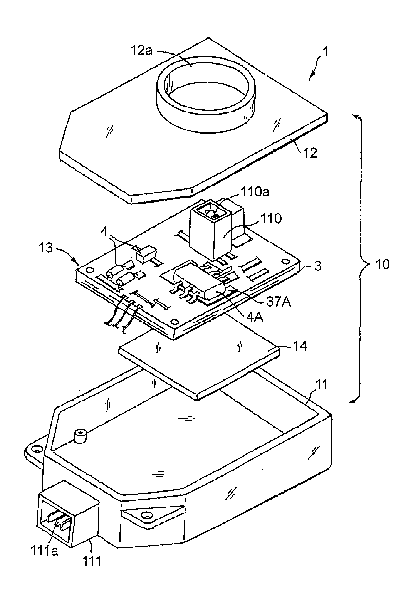
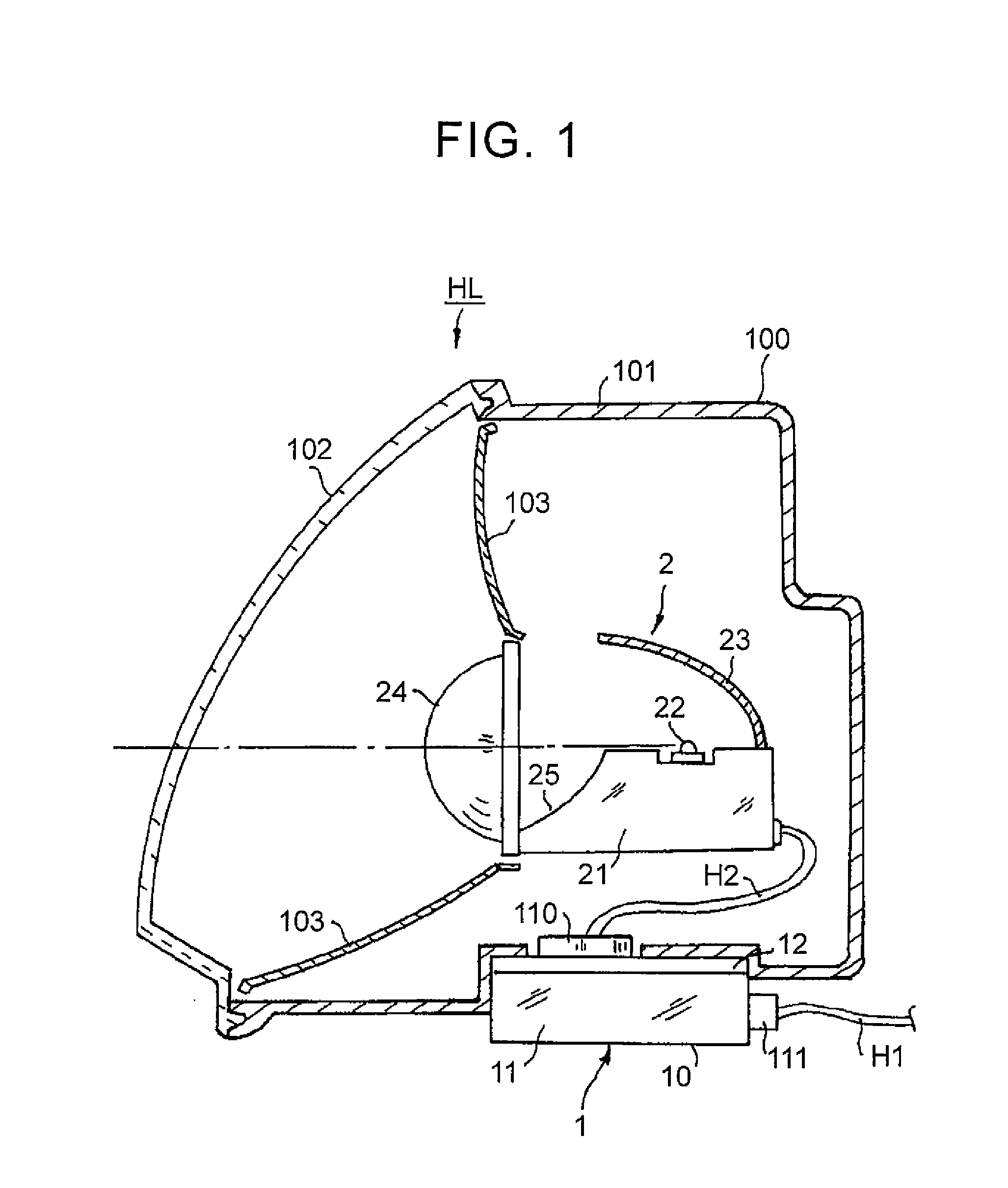
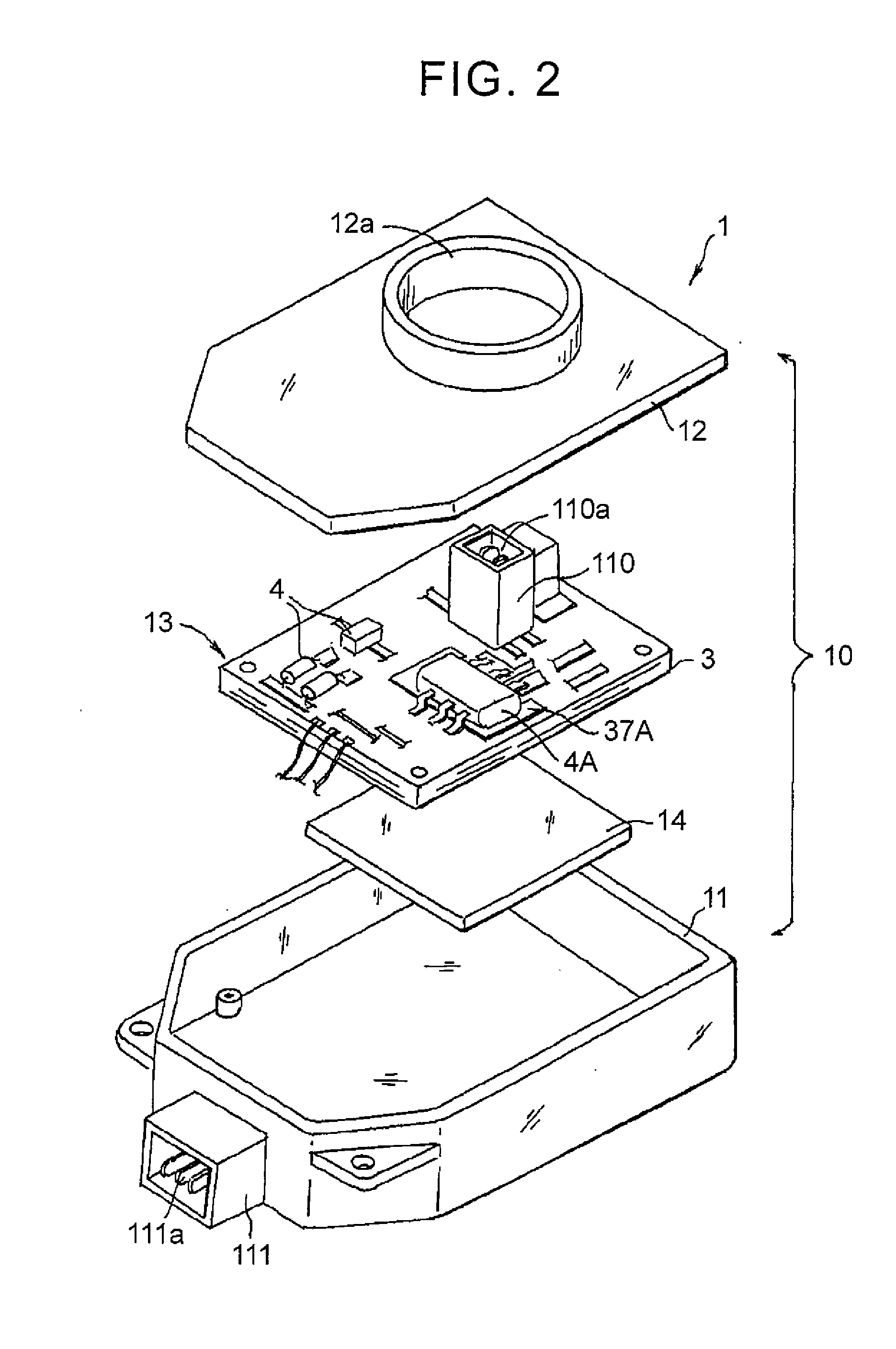
[0017]Example embodiments of the invention will now be described with reference to the accompanying drawings. FIG. 1 is a sectional view schematically showing a first example embodiment in which the electronic unit of the invention is used as an electronic unit that performs lighting control of a headlamp of a vehicle. A lamp housing 100 of a headlamp HL is formed by a lamp body 101 and a front cover 102. A light source unit 2 is arranged together with an extension (pseudo reflector) 103, inside the lamp housing 100. Also, an electronic unit 1 is provided on an external portion of the lamp housing 100, as a lighting control unit for lighting the light source of this light source unit 2, as well as for controlling the lighting state of the light source of this light source unit 2. This electronic unit 1 is mounted to an outer bottom surface of the lamp body 101 in this case.
[0018]The light source unit 2 is formed as a so-called projector-type lamp unit. That is, the light source unit...
PUM
 Abstract
Description
Claims
Application Information