High efficiency ocean thermal difference power generating system using liquid-vapor ejector and motive pump

Active Publication Date: 2016-11-24
KOREA INST OF OCEAN SCI & TECH
View PDF4 Cites 2 Cited by
  • Summary
  • Abstract
  • Description
  • Claims
  • Application Information

AI Technical Summary

Benefits of technology

The present invention provides a system for generating power using a distributor, liquid-vapor divider, liquid-vapor ejector, and motive pump. This system increases efficiency and decreases the size of the evaporator by controlling the amount of wet vapor at the outlet part of the evaporator. Additionally, the system reduces the amount of refrigerant required at the evaporator by using the distributor to distribute a large amount of refrigerant. Furthermore, the system increases the pressure of the refrigerant flowed into the motive part of the liquid-vapor ejector, which decreases the pressure at the inlet part of the liquid-vapor ejector, resulting in increased turbine generating power and increased system efficiency.

Problems solved by technology

However, it is quite difficult to satisfy the condition for the surface seawater being used in the ocean thermal difference power generation system during all seasons around, because the temperature of the surface seawater around the Korean peninsula is up to or higher than 25° C. during summer season only because of the climate feature of the Korean peninsula.
However, there still exist problems to realize the ocean thermal difference power generation system because the temperature difference between the surface seawater as high heat source and the deep seawater as low heat source is still around 25° C. which does not meet the condition and the expected power efficiency for the power generation systems compared with other kinds of power generation systems, and further, its commercialized step is still composed of first and simple cycle operation and requires more efficient power generation system and its development efforts.

Method used


Image

  • High efficiency ocean thermal difference power generating system using liquid-vapor ejector and motive pump
  • High efficiency ocean thermal difference power generating system using liquid-vapor ejector and motive pump
  • High efficiency ocean thermal difference power generating system using liquid-vapor ejector and motive pump

Examples


Embodiment Construction

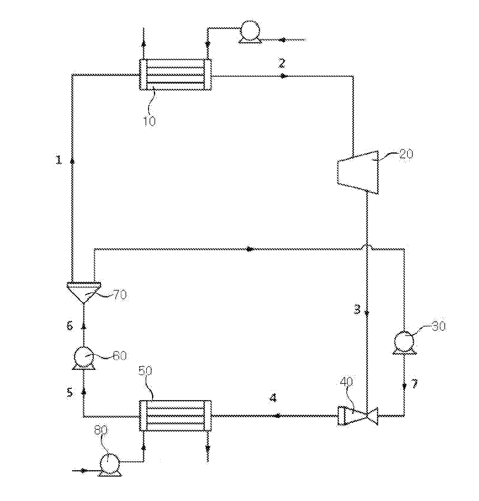
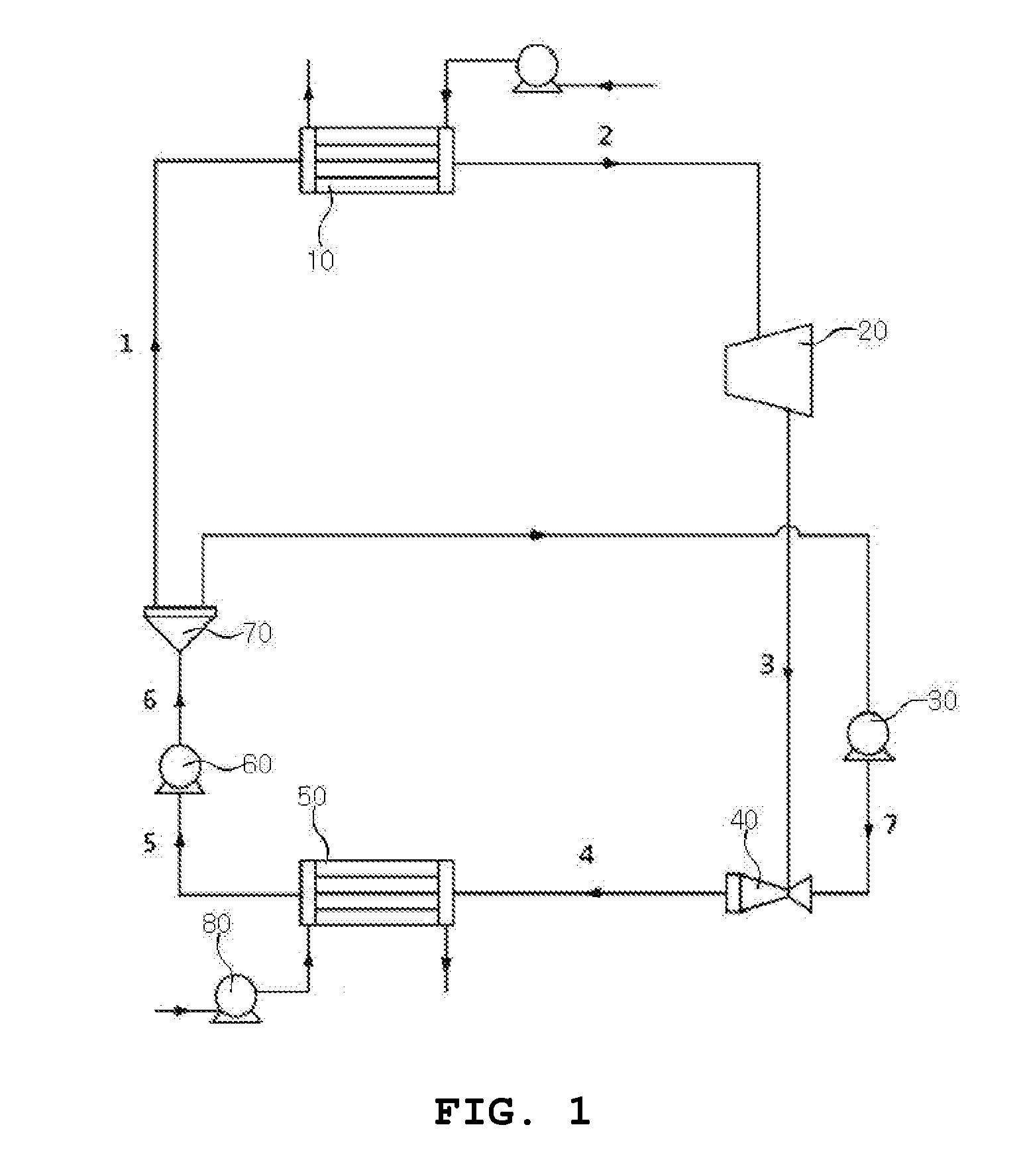
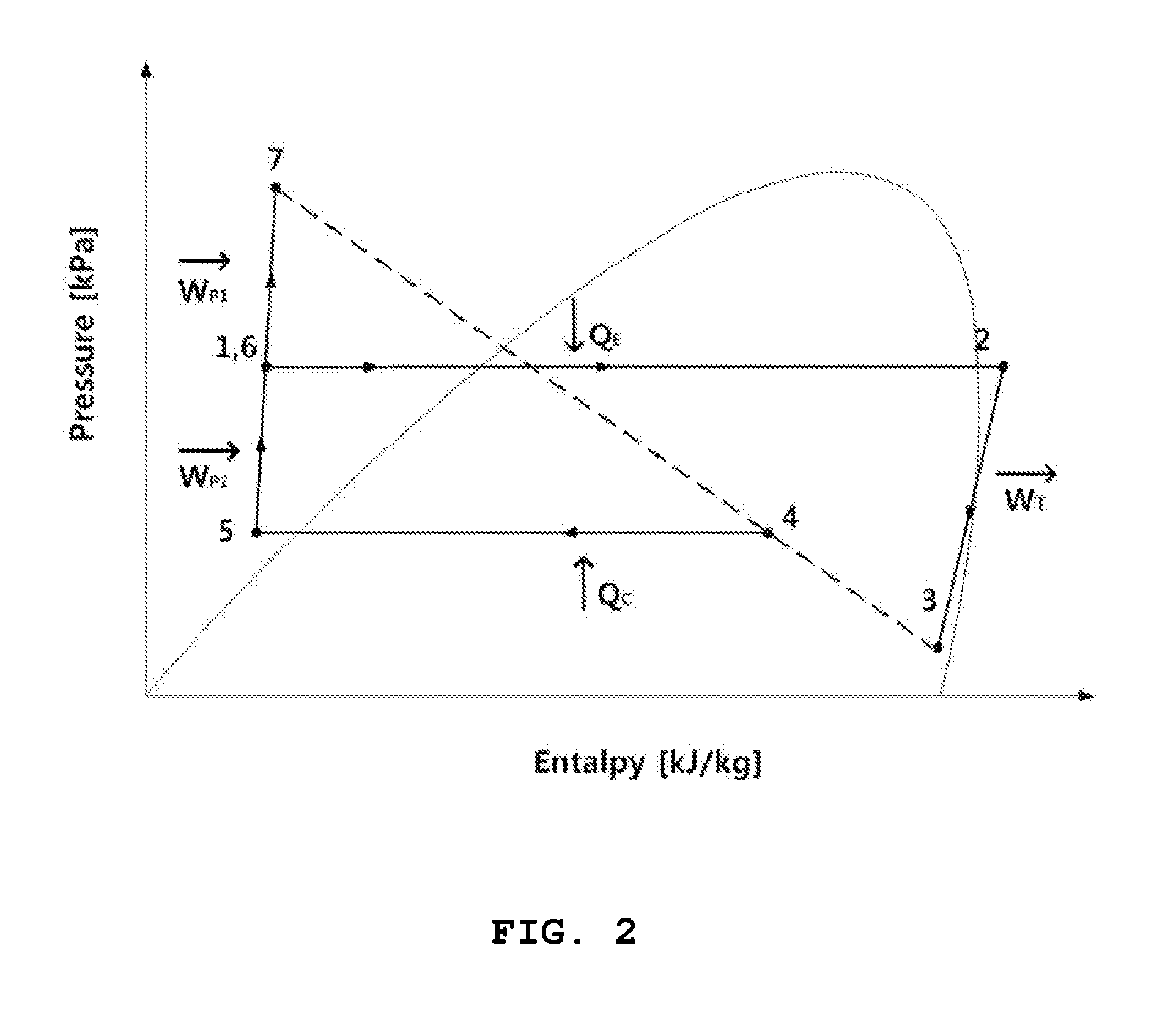
[0018]The present invention will now be described more fully hereinafter with reference to the accompanying drawings, in which preferred embodiments of the invention are shown.

[0019]It will be understood that words or terms used in the specification and claims shall not be interpreted as the meaning defined in commonly used dictionaries. It will be further understood that the words or terms should be interpreted as having a meaning that is consistent with their meaning in the context of the relevant art and the technical idea of the invention, based on the principle that an inventor may properly define the meaning of the words or terms to best explain the invention.

[0020]As used herein, the singular forms “a”, “an” and “the” are intended to include the plural forms as well, unless the context clearly indicates otherwise.

Terms indicating directions of apparatuses or elements (such as “front”, “back”, “up”, “down”, “top”, “bottom”, “left”, “right”, and “lateral”) are used to simplify ...


PUM


Abstract

There is provided a high efficiency ocean thermal difference power generating system by using liquid-vapor ejector and motive pump comprising: an evaporator for changing transferred refrigerant liquid into refrigerant vapor with high temperature and high pressure by the thermal exchange with surface seawater; a vapor-liquid divider which is installed at the outlet part of the evaporator and divides the refrigerants to liquid-state refrigerant and vapor-state refrigerant respectively; a distributor which is installed at the inlet of the evaporator and distributes the refrigerants flowed into the evaporator to multi-paths; a turbine for generating electric power by using the high pressure refrigerant vapor transferred from the liquid-vapor divider or the evaporator; a motive pump for increasing the pressure of the refrigerant liquid distributed from the distributor or the liquid-vapor divider; a liquid-vapor ejector for mixing the low pressure refrigerant vapor which passed the turbine and the high pressure refrigerant liquid which passed a motive pump, thereby proceeding expansion and compression; a condenser for condensing the refrigerants which was mixed in the liquid-vapor ejector by the thermal exchange with deep seawater; and a refrigerant circulation pump for increasing the pressure of the refrigerants which was condensed in the condenser up to the evaporation pressure and for circulating.

Description

TECHNICAL FIELD[0001]The present invention relates to an ocean thermal difference power generating system for further increasing the efficiency of its system cycle by installing a motive pump to a motive part of a liquid-vapor ejector thereby to provide the effect of increasing its power generating efficiency compared with the existing ocean thermal difference power generating systems and for further increasing generated power energy by providing a lower turbine output pressure than that of the existing ocean thermal difference power generating system with the turbine outlet being connected to an inlet part of the ejector, and additionally, for increasing the pressure of the liquid-state working fluid going into the motive part of the ejector by a pump, thereby to provide increased power amount with the greater pressure difference between the inlet and outlet parts of the turbine and increased system efficiency, and more particularly, a high efficiency ocean thermal difference power...

Claims


Application Information

Patent Timeline
IPC IPC(8): F03G7/05F01K7/16
CPCF01K7/16F03G7/05F01K5/00Y02E10/30
Inventor KIM, HYEON-JULEE, HO-SAENGCHA, SANG-WONJUNG, YOUNG-KWONYOON, JUNG-INSON, CHANG-HYOSEOL, SEONG-HUNYE, BYEONG-HYO
Owner KOREA INST OF OCEAN SCI & TECH
Why Eureka
Try Eureka