
Joint-cycle high-efficiency fuel cell system with power generating turbine

Inactive Publication Date: 2005-07-26
NUVERA FUEL CELLS
View PDF68 Cites 23 Cited by
  • Summary
  • Abstract
  • Description
  • Claims
  • Application Information

AI Technical Summary

Benefits of technology

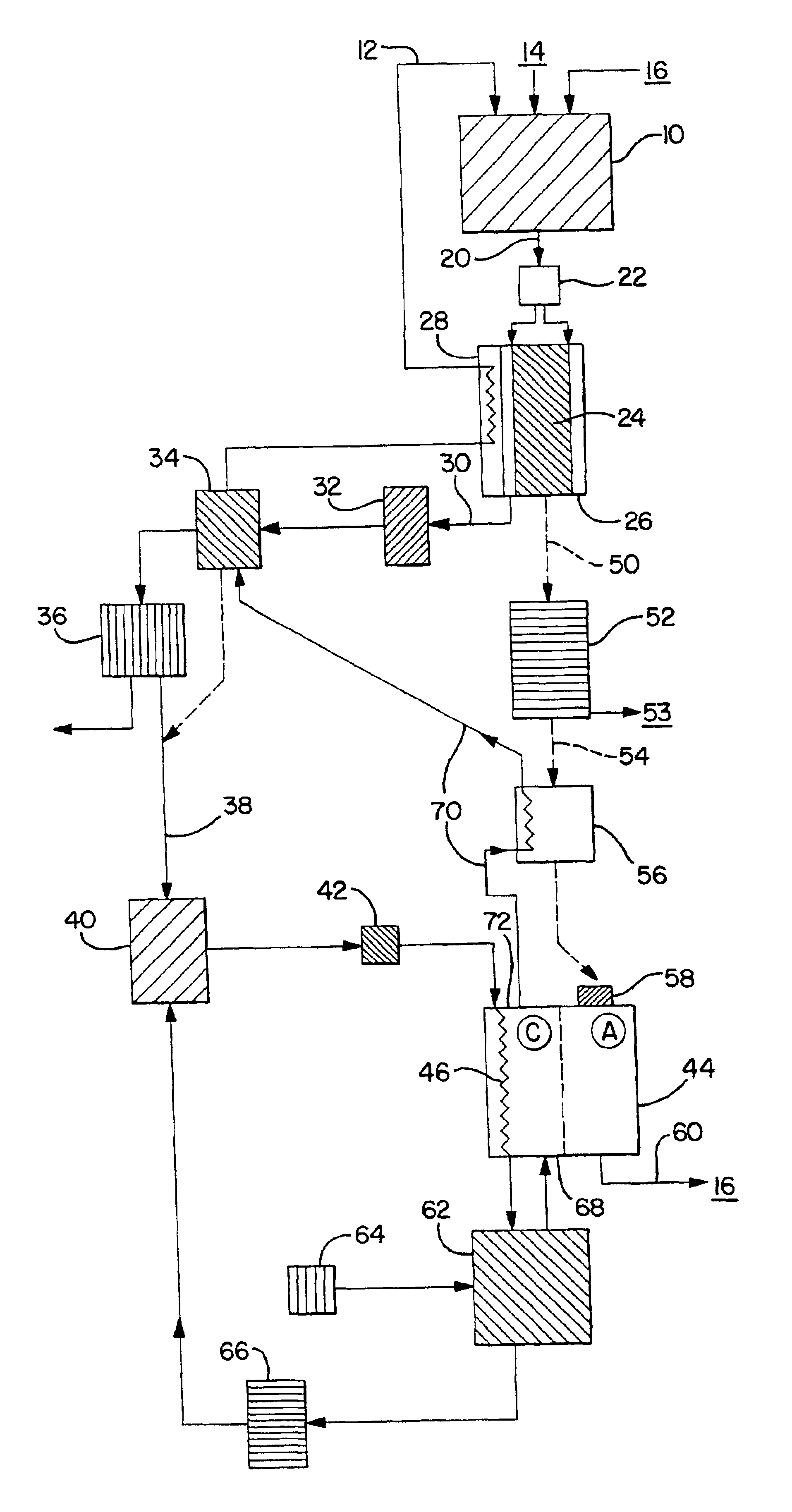
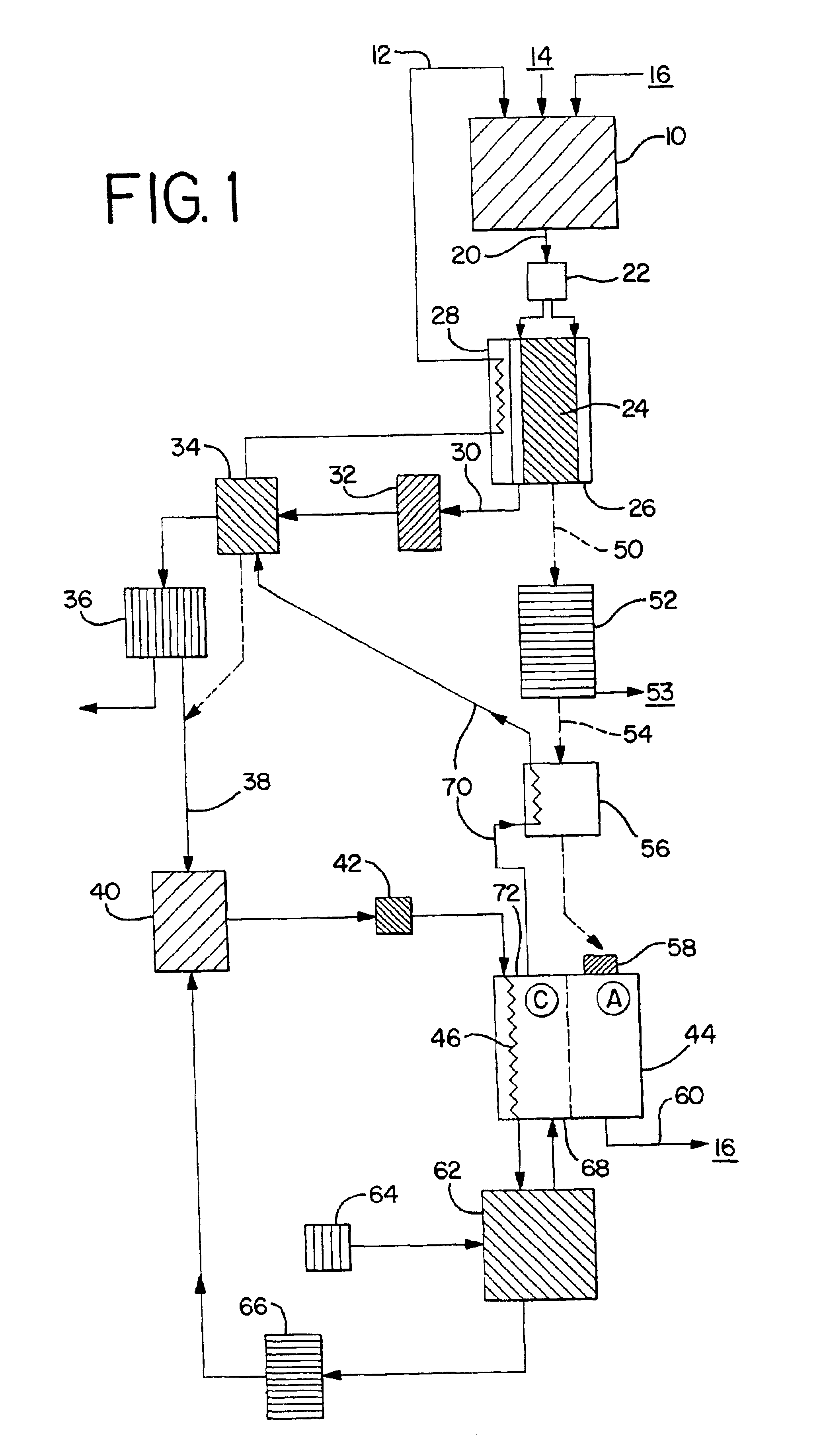
[0013]Generally, the present invention is described as both a method and apparatus for increasing the efficiency of a power system incorporating a fuel cell and a fuel reformer. The increased efficiency is achieved by recovering the heat produced by a fuel cell and capturing it to do useful work in the overall system. The added, preferably mechanical energy is supplemental to the fuel cell power output—without increasing fuel input—thereby increasing overall system efficiency.
[0016]It is still a further aspect of the present invention to provide systems for control of disclosed methods and devices for efficient operation of such systems, particularly in the presence of variable demand for electric output, and more particularly during startup of the system from a cold condition.

Problems solved by technology

The carbon monoxide (CO) is an unwanted byproduct, and, in addition, is difficult to eliminate sufficiently to avoid poisoning the fuel cell.
In a small or mobile system, this is not necessarily practical.
However, the heat generated by the latter two reactions is typically not at a high enough temperature, and may be inadequate in quantity, to run the former two reactions at reasonable rates.
Several U.S. patents teach the combination of turbines and fuel reformers, but these systems are limited to the recouping of some of the work used to pressurize reactants.
Despite improvements and refinements in such systems, the reformer / fuel cell combination is still not sufficiently efficient to be competitive with turbo-compounded internal combustion in many applications.

Method used


Image

  • Joint-cycle high-efficiency fuel cell system with power generating turbine
  • Joint-cycle high-efficiency fuel cell system with power generating turbine
  • Joint-cycle high-efficiency fuel cell system with power generating turbine

Examples


Embodiment Construction

[0026]The features and details of the method and apparatus of the invention will now be more particularly described with reference to the accompanying drawings and pointed out in the claims. The same numeral present in different figures represents the same item. It will be understood that the particular embodiments of the invention are shown by way of illustration and not as limitations of the invention. The principal features of this invention can be employed in various embodiments without departing from the scope of the invention. All percentages and parts are by weight unless otherwise indicated.

[0027]While this invention is susceptible of embodiment in many different forms, this disclosure will describe in detail preferred embodiments of the invention. The present disclosure is to be considered as an example of the principles of the invention, and is not intended to limit the broad aspect of the invention to the embodiments illustrated.

[0028]The integrated fuel cell / fuel reforme...


PUM


Abstract

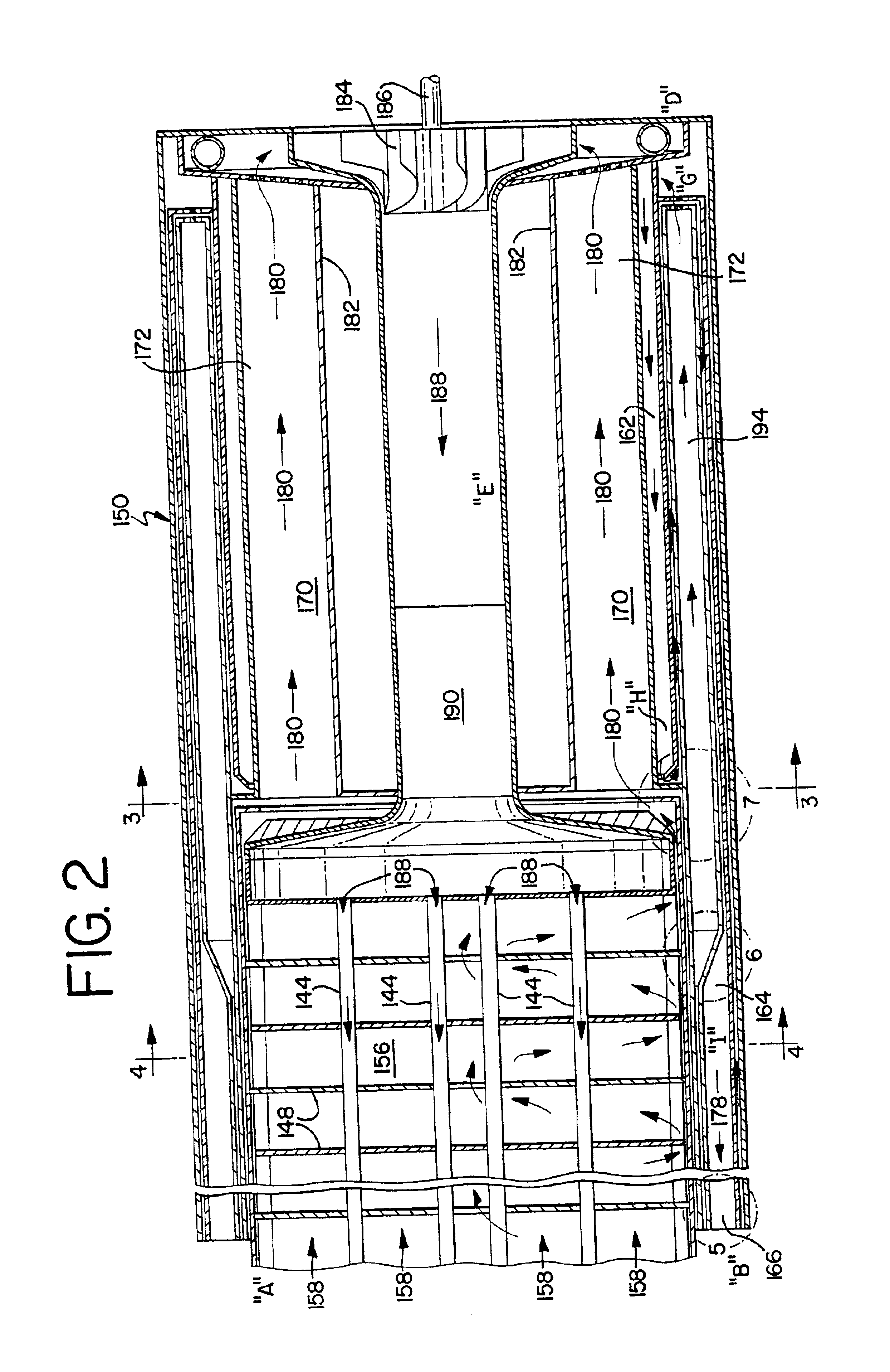
The efficiency of a combination reformer / fuel cell system is significantly improved by recapturing the energy value of heat generated in the fuel cell and producing additional power. The cooling water from the fuel cell is mixed, entirely or in part, with sufficient or excess compressed air, and at least partially evaporates in the compressed air. The air is at least sufficient to support the oxidative reactions in the fuel cell and also to serve as oxidant in a burner that provides heat to reform fuel / steam mixtures into hydrogen-containing reformate. This air / steam mixture, after leaving the fuel cell, is further heated by heat exchange with the reformate stream and reformate-producing modules, and with the exhaust stream of the burner. The steam / air mixture is injected into the burner, optionally after superheating in the burner exhaust, and is reacted with fuel in the burner. The burner exhaust may be used to provide heat to a fuel reforming reaction. The high-temperature burner exhaust may also be used to drive an expander, preferably a turbine, at a location in the system which is downstream of the burner, but in which the exhaust is at a high temperature so as to run the turbine efficiently. The turbine recovers heat energy from the fuel cell as mechanical energy, typically in excess of the energy required to run a compressor, because of the addition of steam to the compressed air. Moreover, system heat removal elements, such as radiators, as well as overall system size and cost, can be markedly reduced for a given level of output.

Description

RELATED APPLICATIONS[0001]This application claims priority of Provisional Application No. 60 / 208,355, filed May 31, 2000.TECHNICAL FIELD OF INVENTION[0002]The present invention is directed to a fuel cell system having improved efficiency. Particularly, the present invention relates to methods and apparatus which use the otherwise waste heat of an operating fuel cell to do useful work. More particularly, the invention uses waste heat to create an air / steam mixture which drives an expander to produce mechanical energy, thereby improving the efficiency of the fuel cell system.BACKGROUND OF THE INVENTION[0003]Fuel cells have become useful energy sources over the last few decades, but wider use of fuel cells requires a continuous available source of hydrogen. One way to provide hydrogen for fuel cells in small or remote locations, or in mobile installations, is as a reformate of a hydrocarbon or oxygenated hydrocarbon fuel, such as natural gas (methane), gasoline, or alcohol. The reformi...

Claims


Application Information

Patent Timeline
IPC IPC(8): F02C3/22F02C3/20H01M2/00H01M8/18H01M8/12H01M8/04H01M8/00H01M8/06H01M
CPCH01M8/04022H01M8/04089H01M8/0612H01M2250/407Y02E60/563Y02E60/50Y02P20/129
Inventor CLAWSON, LAWRENCE G.HAGAN, MARK R.
Owner NUVERA FUEL CELLS
Learn More