
Cache accessing using a micro TAG

Active Publication Date: 2009-09-17
ARM LTD
View PDF8 Cites 5 Cited by
  • Summary
  • Abstract
  • Description
  • Claims
  • Application Information

AI Technical Summary

Benefits of technology

[0014]The present invention recognises the fact that although the information that is needed to identify a cache way that a particular value is stored in is small as there are generally only a few cache ways to discriminate between, the information needed to identify the cache line is large and thus, an important amount of logic is required for each of the entries storing the cache way information in order to be able to identify which entry is relevant for a particular cache line. The present invention also recognises that although most data stores storing this information typically store information relating to the most recently accessed addresses as these are most likely to be accessed again, in many circumstances accesses are performed to a particular region of memory during a particular period of time. Thus, were the data store storing the cache way information to be made to store not the most recently accessed cache addresses but values relating to a particular region of memory in which a recently accessed cache address is located then accesses could be performed without the need to identify each location using the cache line address. In particular, by storing in the data store values relating to consecutive addresses then the required entry can be determined simply from an offset to the previous access. A current pointer could then be moved by that offset amount, and provided the current pointer did not move out of the address region covered by the data store it would point to the new entry. This has the advantage of requiring only a few bits to determine a new entry location and thus, more entry locations could be provided and a larger memory region covered by the data store for a similar amount of logic. This could increase the efficiency of the system and significantly reduce the number of TAG RAM lookups required when there is no entry in the microtag.

Problems solved by technology

The storage of a large amount of data can make accessing the data within the cache quite a complicated procedure which requires addresses of a relatively large size.
Manipulation of such addresses can therefore require significant amounts of power and time.
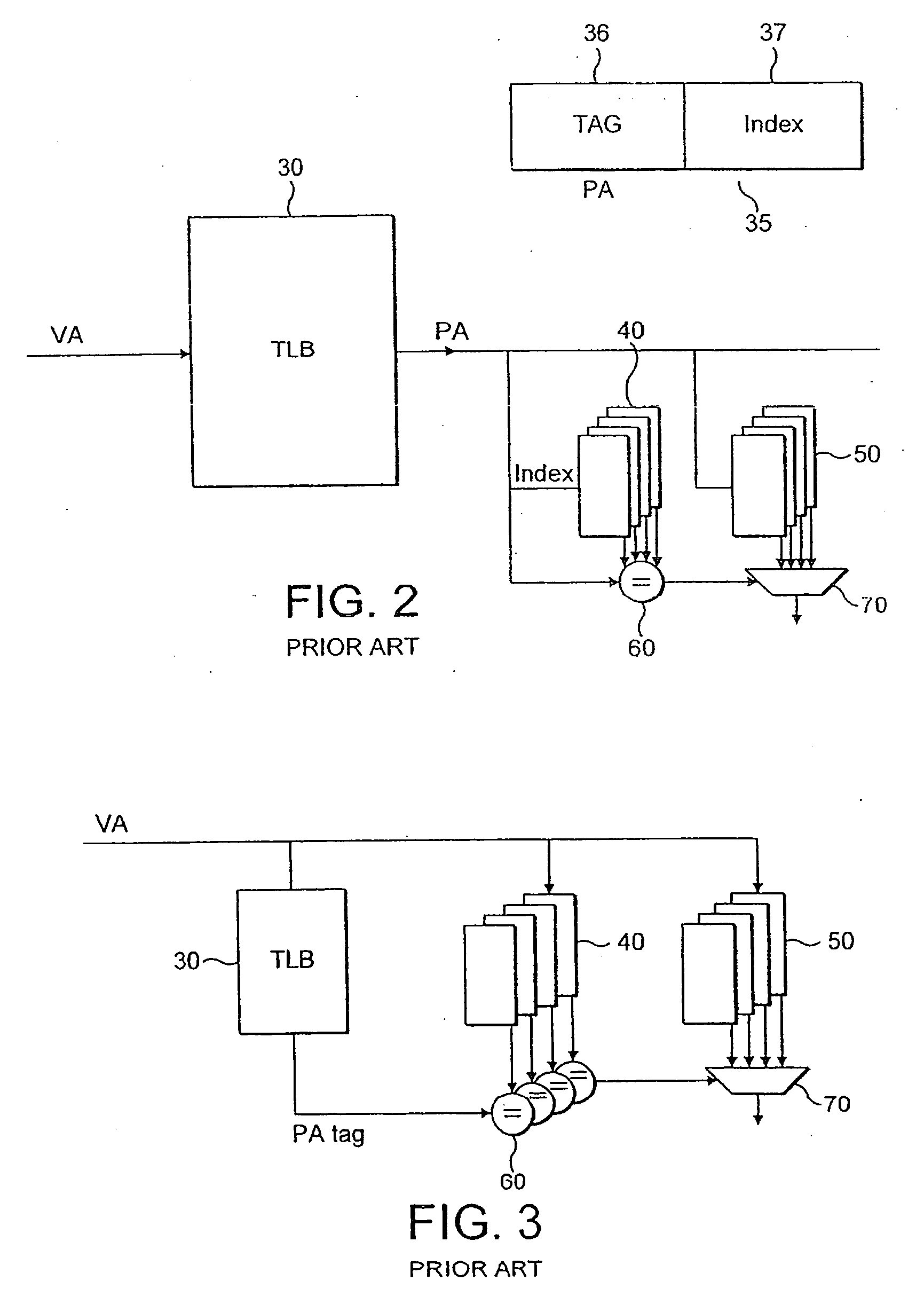
This can slow the procedure, as the program will produce the virtual address early, but the data cannot be accessed until it is converted to a physical address.
This is not a fast step and thus, having this as the first step in the procedure considerably slows the critical path.
Thus, the comparison stage can be slow.
Furthermore, this process requires the accessing of multiple RAMs i.e. multiple cache tag directories and cache data arrays (RAMs) are accessed during the procedure and power consumption is therefore high.
Thus, this solution is expensive in storage particularly if cache access information for several recent cache accesses is stored.

Method used


Image

  • Cache accessing using a micro TAG
  • Cache accessing using a micro TAG
  • Cache accessing using a micro TAG

Examples


Embodiment Construction

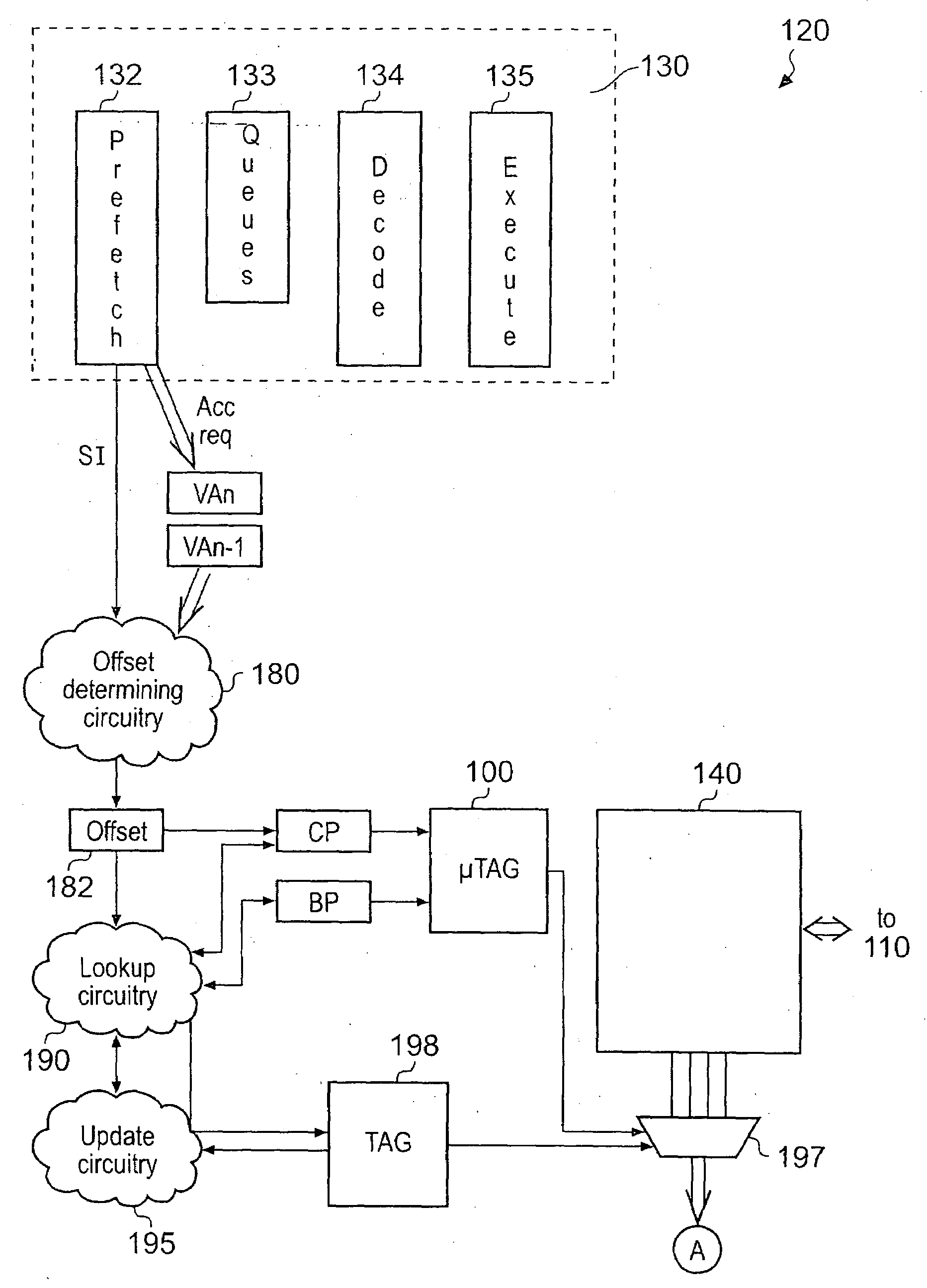
[0045]FIG. 4 shows microtag 100 which stores values indicating cache ways for a region of memory 110. Microtag 100 has n entries for storing n values indicating the cache ways for n consecutive addresses within memory 110 and comprises two pointers associated with it that point to two entries within microtag 100. One pointer is the bottom pointer which points to the lowest address covered by microtag 100 and the other is the current pointer which points to the location corresponding to the current cache access request being processed. In the case of an instruction cache this points to the same address as the program counter.

[0046]FIG. 5 shows a data processing apparatus 120 according to an embodiment of the present invention. Data processing apparatus 120 comprises a processor 130, having a prefetch unit 132, instruction queues 133, decode section 134 and an execution section or sections 135. There is an instruction cache 140 that prefetch unit 132 fetches instructions from and a me...


PUM


Abstract

A data processing apparatus is disclosed that comprises: at least one data processor for processing data; a set associative cache for storing a plurality of values to be processed by said data processor, each value being identified by an address of a memory location within a memory storing said value, said set associative cache being divided into a plurality of cache ways; a data store comprising a plurality of storage locations for storing a plurality of identifiers, each identifier identifying a cache way that a corresponding value from said set associative cache is stored in and each having a valid indicator associated therewith, said plurality of identifiers corresponding to a plurality of values, said plurality of values being values stored in consecutive addresses such that said data store stores identifiers for values stored in a region of said memory; current pointer store for storing a current pointer pointing to a most recently accessed storage location in said data store; offset determining circuitry responsive to a cache access request to determine an offset of an address of said cache access request to an immediately preceding cache access request, said offset determining circuitry being adapted to update said current pointer by said offset amount; and data store lookup circuitry for determining from a size of said data store and said offset if said updated current pointer is pointing to an address within said region and if so said data processor is adapted to identify said cache way from said stored identifier pointed to by said current pointer if it has a valid indicator associated with it.

Description

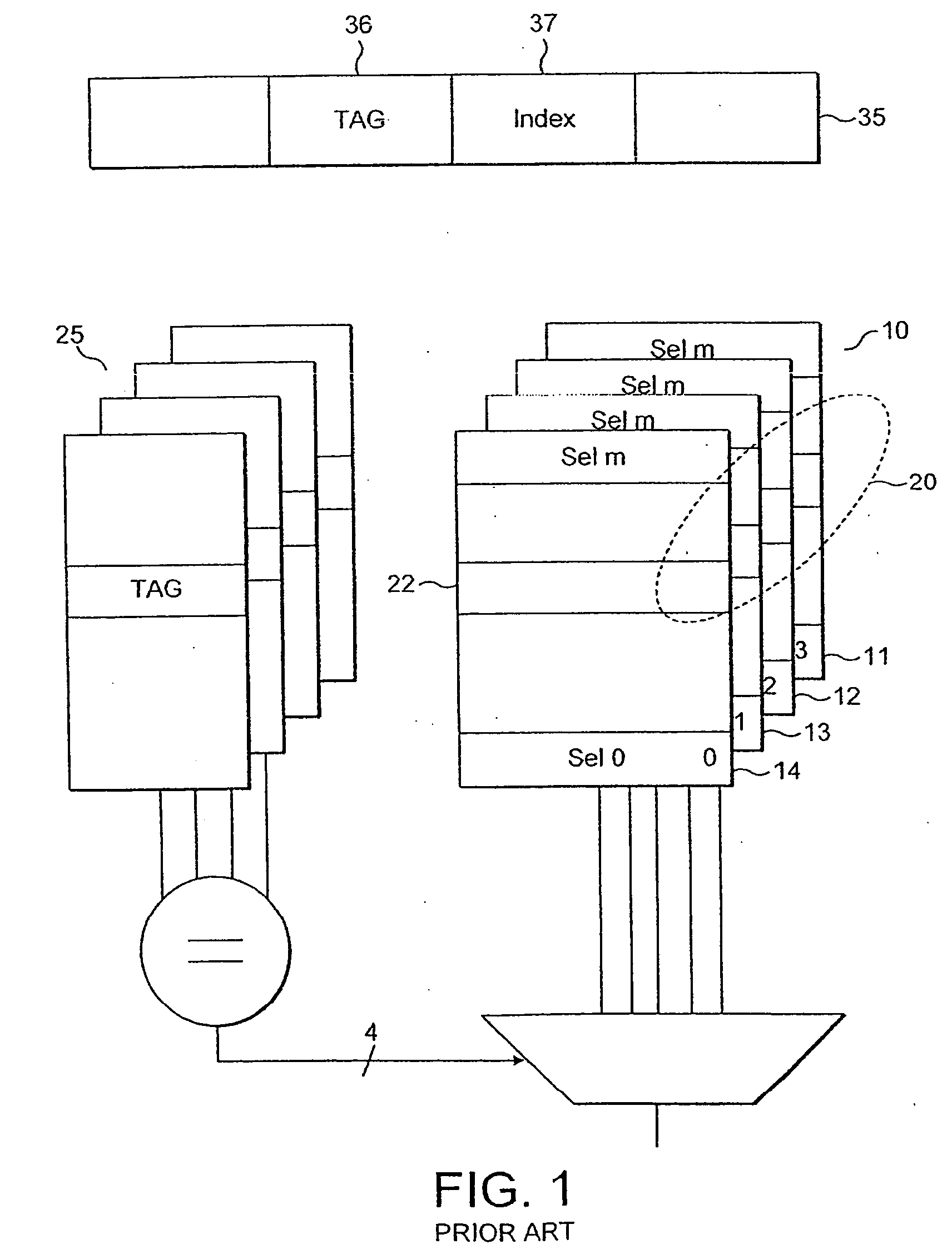
BACKGROUND OF THE INVENTION[0001]1. Field of the Invention[0002]The present invention relates to accessing a cache using a micro tag.[0003]2. Description of the Prior Art[0004]Caches are used within data processing apparatus to store increasingly large amounts of data. The storage of a large amount of data can make accessing the data within the cache quite a complicated procedure which requires addresses of a relatively large size. Manipulation of such addresses can therefore require significant amounts of power and time. Caches have been organised in a number of ways in order to reduce power and time overheads involved in accessing storage locations within them.[0005]One popular way of configuring a cache is the so-called ‘set associative’ cache. A 16 Kbyte set associative cache is shown in FIG. 1. The cache shown is such a 4-way set associative cache 10 having 4 ways 11, 12, 13, 14 each containing a number of cache lines 20. A data value (in the following examples, a word) associa...

Claims


Application Information

Patent Timeline
IPC IPC(8): G06F12/08G06F12/00G06F12/0864G06F12/0895G06F12/1045
CPCG06F12/0864G06F12/0895G06F12/1045
Inventor MOUTON, LOUIS-MARIE VINCENTHUOT, NICOLAS JEAN PHILLIPPEGRANDOU, GILLES ERICBROCHIER, STEPHANE ERIC SEBASTIAN
Owner ARM LTD
Learn More