
Optical mouse system with illumination guide having a light spreading lens

Inactive Publication Date: 2007-08-16
PIXON TECH CORP
View PDF8 Cites 19 Cited by
  • Summary
  • Abstract
  • Description
  • Claims
  • Application Information

AI Technical Summary

Benefits of technology

[0014] To achieve these and other advantages and in order to overcome the disadvantages of the conventional method in accordance with the purpose of the invention as embodied and broadly described herein, the present invention provides an optical mouse system that directs illumination at a surface from an angle of typically less than about thirty-three degrees in respect to a 90 degree angle from the surface, thereby increasing the optical efficiency of the system and reducing power requirements, and also thereby increasing the sensitivity of the system to the relative movement of the reference surface, and also thereby shrinking size requirements.
[0016] When light passes through a convex lens, the convex lens causes light rays to refract convergently. This therefore creates a light pattern that is focused into a small point of light. This compact, high contrast, light pattern creates problems for the sensor and can cause the sensor to misinterpret motion of the mouse.
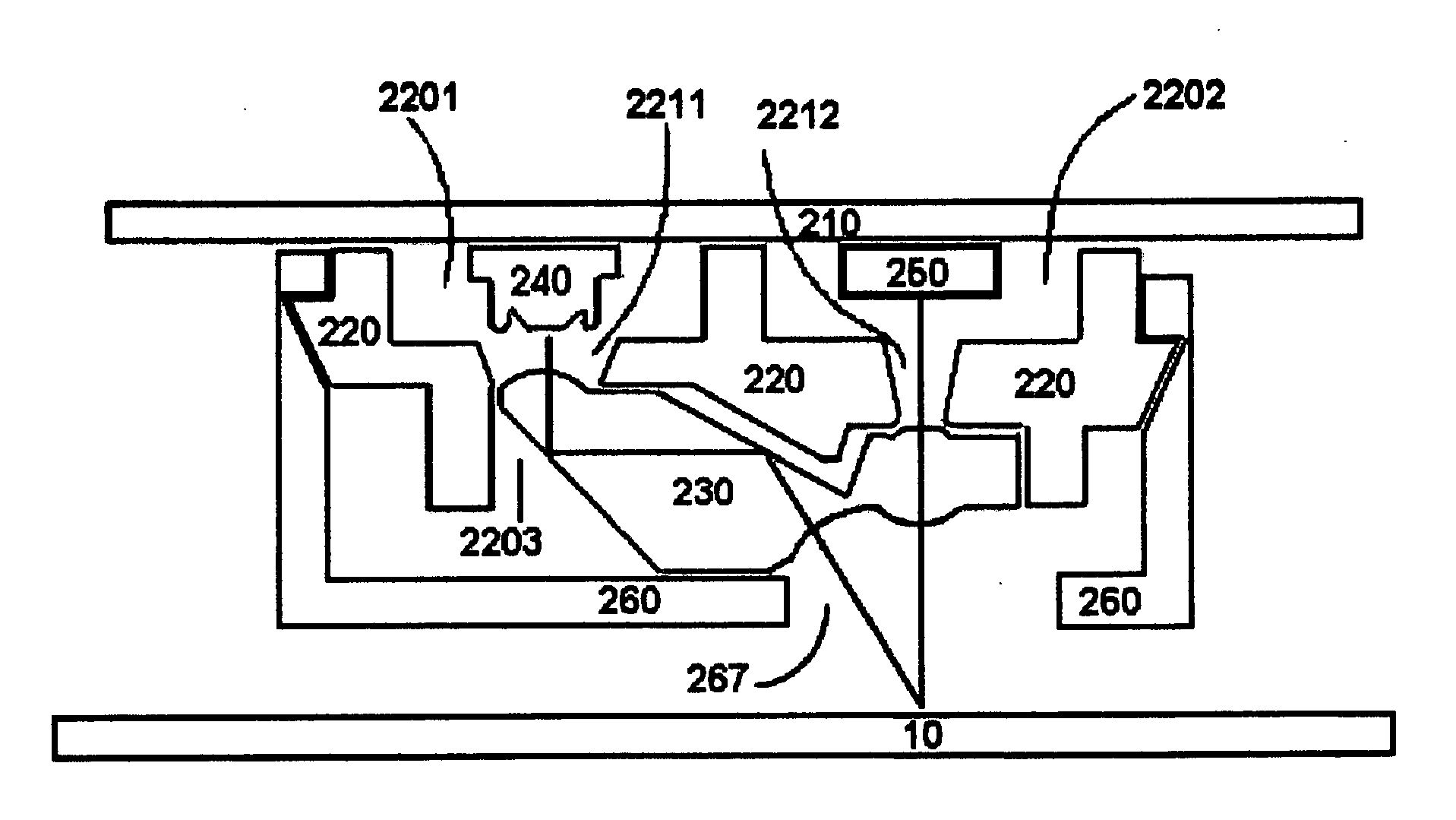
[0017] However, a concave surface causes light rays to refract divergently. As a result, the light is spread and creates a uniform and low contrast illumination pattern. This allows the sensor to more accurately sense motion of the mouse. As a result, the cursor representing mouse position moves across the screen more accurately and smoothly. As a result, computer user satisfaction is increased.
[0018] The present invention further provides an optical mouse system in which the illumination source is mounted on the same surface or plane as the optical sensor, thereby simplifying construction and shrinking size requirements.
[0019] The present invention further provides an optical mouse system in which the optical sensor may optionally be substantially isolated from extraneous light, both that which is generated by the mouse and that which is foreign to the system, thereby increasing the sensitivity of the system to the relative movement of the reference surface.

Problems solved by technology

This compact, high contrast, light pattern creates problems for the sensor and can cause the sensor to misinterpret motion of the mouse.
However, a concave surface causes light rays to refract divergently.

Method used


Image

  • Optical mouse system with illumination guide having a light spreading lens
  • Optical mouse system with illumination guide having a light spreading lens
  • Optical mouse system with illumination guide having a light spreading lens

Examples


Embodiment Construction

[0032] Reference will now be made in detail to the preferred embodiments of the present invention, examples of which are illustrated in the accompanying drawings. Wherever possible, the same reference numbers are used in the drawings and the description to refer to the same or like parts.

[0033] Please refer to FIG. 2a, which shows a cross-section diagram of the internal components of an optical computer mouse according to an embodiment of the present invention. The cross-section traverses the exit aperture 2211 and entry aperture 2212, thereby causing the holder 220 to appear as if in three pieces.

[0034] An illumination source 240 and an optical sensor 250 are mounted on a printed-circuit board (PCB) 210. The illumination source 240 is typically a light-emitting diode (LED) in the SMD form factor, but the present invention may also use an infrared-emitting diode, a laser diode, or other suitable illuminating radiation emission source matched to the type of illumination that the op...


PUM


Abstract

An optical mouse system with an illumination guide includes a concave lens for spreading light to create a uniform, low contrast, illumination pattern. The uniform illumination pattern increases the accuracy of mouse movement detected by the sensor. The illumination source and optical sensor are mounted in the same plane, directly on the PCB. The higher angle of the optical path causes more light to be reflected to the optical sensor, increasing optical efficiency and allowing a smaller, lower powered LED to be used. This also results in increased sensitivity of the optical sensor. Lower power usage increases battery life for mobile or wireless-mouse use, while reducing thermal waste considerations. This allows the creation of a significantly smaller form factor for the overall package, thereby reducing materials costs and giving designers more flexibility for external design considerations.

Description

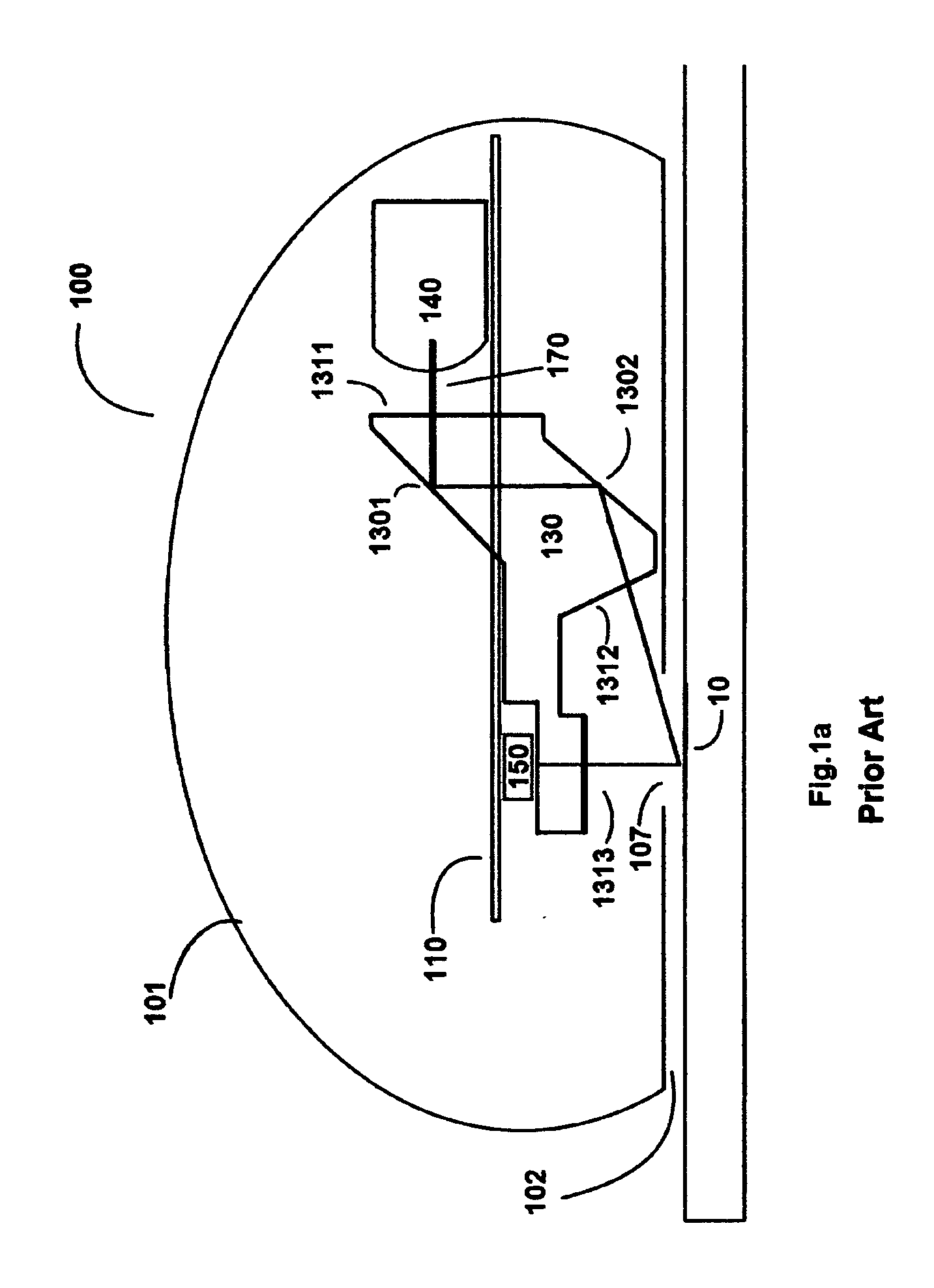
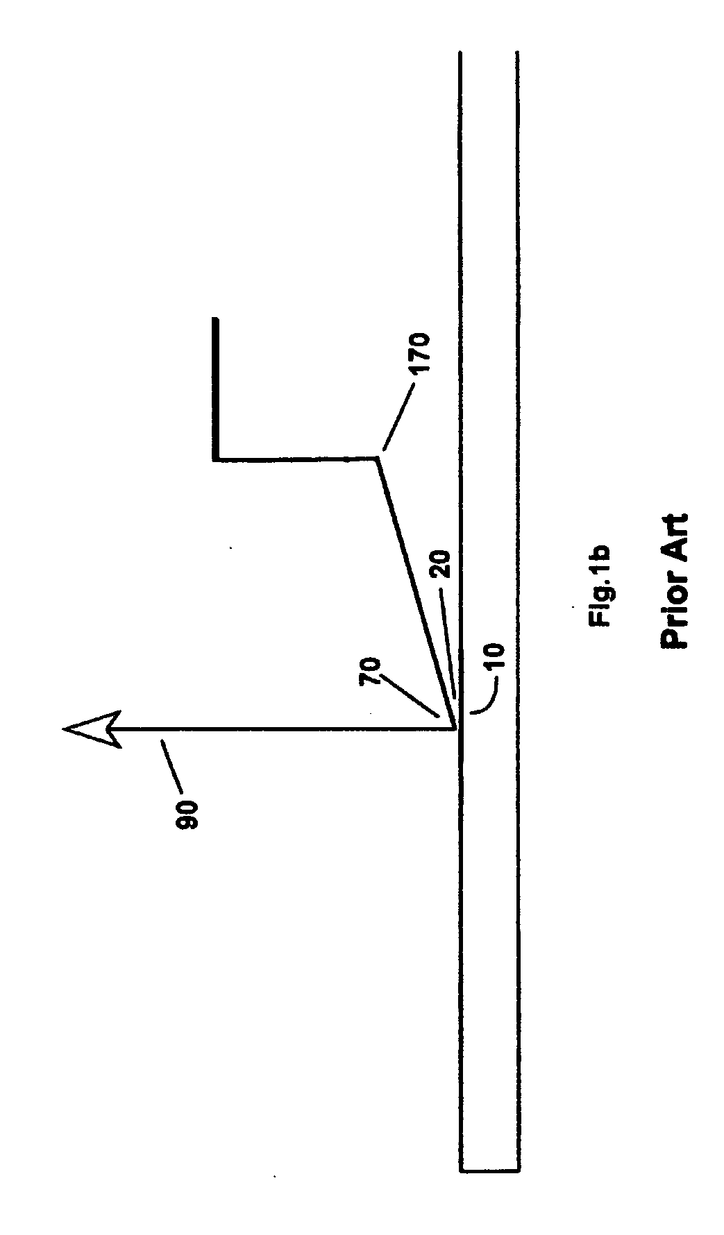
BACKGROUND OF THE INVENTION [0001] 1. Field of the Invention [0002] The present invention relates to optics. More specifically, the present invention discloses an optimized optical system comprising an optical mouse illumination guide with a concave lens for spreading light to create a uniform, low contrast, illumination pattern. [0003] 2. Description of the Prior Art [0004] Traditionally, an optical computer mouse uses a light-emitting diode (LED) to graze a surface with illuminating light, and detects patterns in reflected light from the surface to compute motion. [0005] Please refer to FIG. 1a, a diagram of a prior-art optical computer mouse 100. Externally, the mouse has a housing 101 and a base plate 102. Internal to the housing, a printed-circuit board (PCB) 110 has a light-emitting diode 140 (LED) and optical sensor 150 mounted to it. The LED 140 emits light, a light beam 170 of which is focused and guided through an illumination guide 130. The illumination guide 130 typicall...

Claims


Application Information

Patent Timeline
IPC IPC(8): G09G5/08G06F3/0354
CPCG06F3/0317
Inventor WU, RONG YAWCHENG, SHU YINGCHEN, SHIH CHE
Owner PIXON TECH CORP
Learn More