Unlock instant, AI-driven research and patent intelligence for your innovation.

Robot apparatus and position and orientation detecting method

a robot and position detection technology, applied in the field of robot apparatus and position and orientation detection methods, can solve the problems of enormous time consumed by the object detection apparatus to assume accurate position and orientation of the target object, and achieve the effect of estimating the position and orientation of the object in a shorter tim

Active Publication Date: 2015-07-14
SEIKO EPSON CORP
View PDF10 Cites 1 Cited by
  • Summary
  • Abstract
  • Description
  • Claims
  • Application Information

AI Technical Summary

Benefits of technology

The patent describes a robot apparatus and a method to detect the position and orientation of an object quickly using a three-dimensional model. The robot apparatus includes a detailed detection unit that accurately detects the position and orientation of the object and controls the robot. The method allows for easy creation of a reference model based on a design drawing or CAD drawing. The technical effects of this invention include faster position and orientation estimation and improved accuracy of robot control.

Problems solved by technology

Therefore, the object detecting apparatus consumes enormous time to assume accurate position and orientation of the target object.

Method used


Image

  • Robot apparatus and position and orientation detecting method
  • Robot apparatus and position and orientation detecting method
  • Robot apparatus and position and orientation detecting method

Examples


first embodiment

[0040]A robot system according to a first embodiment of the invention is a system that obtains the photographed image of the target object, and, on the basis of the photographed image, controls the position and the orientation of a gripping unit attached to a robot main body to move the gripping unit toward a target object.

Configuration of the Robot System

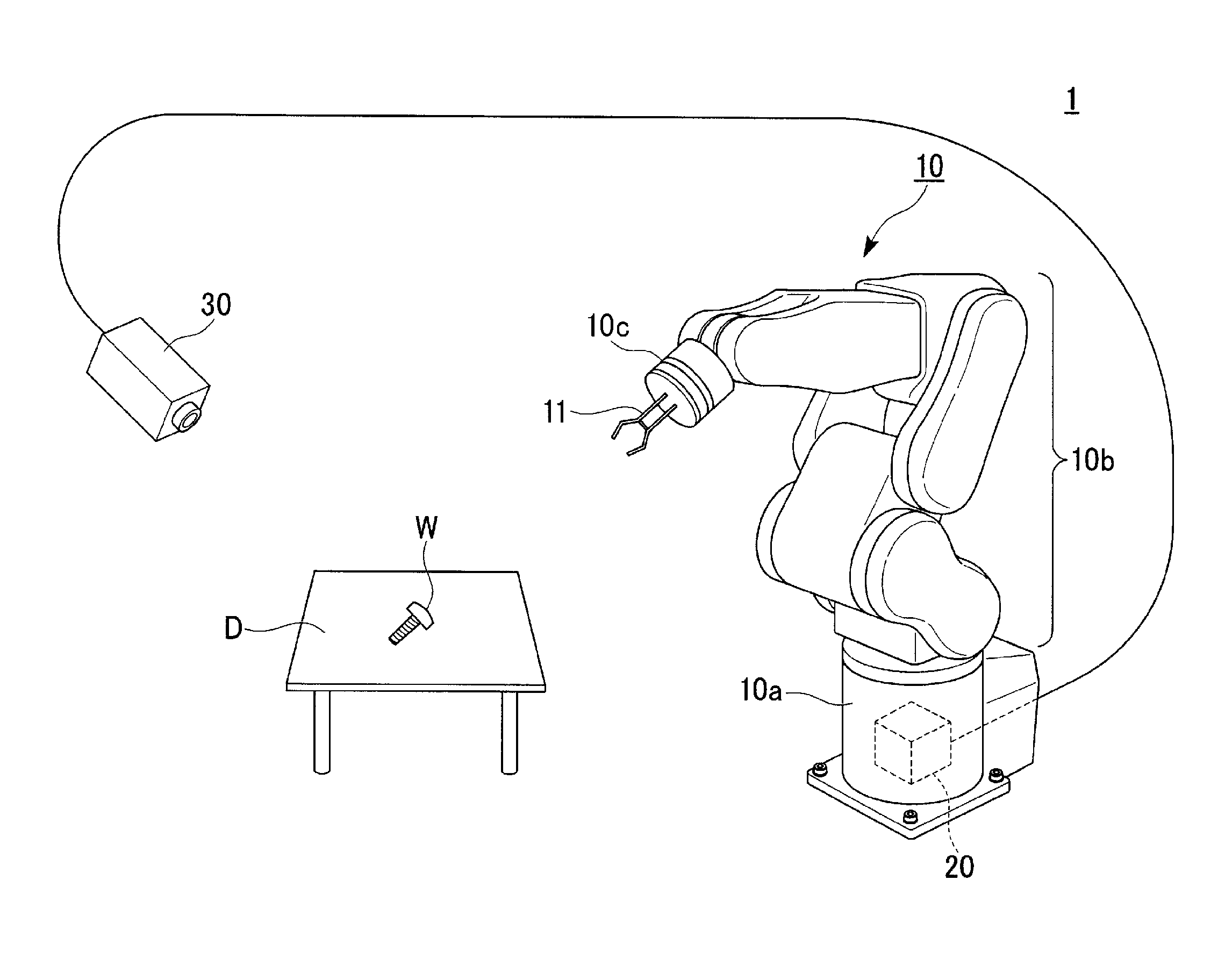
[0041]FIG. 1 is a schematic external view showing a state in which a robot system, to which a robot apparatus and a position and orientation detecting device according to the first embodiment of the invention are applied, performs work.

[0042]In the figure, the robot system 1 includes a robot main body 10, a gripping unit 11, a robot control device 20 housed on the inside of the robot main body 10, and a photographing device 30. The robot main body 10 and the robot control device 20 are included in a robot apparatus.

[0043]The robot main body 10 includes the gripping unit movably. The gripping unit 11 includes a claw unit capable of ...

second embodiment

[0103]In a robot system according to a second embodiment of the invention, a gripping unit attached to a robot main body grips or holds a component in advance. The robot system acquires a photographed image of a main body assembly to which the component is attached, controls the position and the orientation of the gripping unit on the basis of the photographed image, and moves the gripping unit to the main body assembly.

[0104]FIG. 8 a schematic external view showing a state in which a robot system, to which a robot apparatus and a position and orientation detecting device according to the second embodiment are applied, performs work.

[0105]In the figure, a robot system la includes the robot main body 10, the gripping unit 11, the robot control device 20 housed on the inside of the robot main body 10, and the photographing device 30.

[0106]The components of the robot system la is the same as the components in the first embodiment. Therefore, in this embodiment, explanation of the compo...

third embodiment

[0111]In a robot system according to a third embodiment of the invention, a robot main body includes hands of two systems. The robot system acquires a photographed image of a target object with a photographing device attached to one hand of the robot main body and controls, on the basis of the photographed image, the position and the orientation of a gripping unit attached to the other hand to move the gripping unit toward the target object.

[0112]FIG. 9 is a schematic external view showing a state in which a robot system, to which a robot apparatus and a position and orientation detecting device according to the third embodiment are applied, performs work.

[0113]In the figure, a robot system (a robot apparatus) 2 includes a robot main body 40, a photographing device 41, a gripping unit 42, and the robot control device 20 housed on the inside of the robot main body 40.

[0114]The configuration of the robot control device 20 is the same as the configuration in the first embodiment. There...


PUM


Abstract

A robot apparatus includes a reference-model storing unit configured to store a reference model of an object, a feature-value-table storing unit configured to store a feature value table that associates position data and orientation data of the reference model and a feature value, a photographed-image acquiring unit configured to capture a photographed image of the object, a detecting unit configured to calculate a photographed image feature value from the photographed image, and a driving control unit configured to control a robot main body on the basis of the position data and the orientation data to change the position and the orientation of a gripping unit.

Description

BACKGROUND[0001]1. Technical Field[0002]The present invention relates to a robot apparatus and a position and orientation detecting method.[0003]2. Related Art[0004]There is known an object detecting apparatus that collates a target object image obtained by an image pickup apparatus picking up an image of a target object and a three-dimensional shape model registered in advance to thereby detect the position and the orientation of the target object (see, for example, JP-A-2002-157595).[0005]However, the object detecting apparatus in the past to which the three-dimensional shape model is applied calculates the position and the orientation of the target object using six variables indicating translation and rotation in a three-dimensional Cartesian coordinate system in order to estimate the position and the orientation of the target object. Therefore, the object detecting apparatus consumes enormous time to assume accurate position and orientation of the target object.SUMMARY[0006]An a...

Claims


Application Information

Patent Timeline
Patent Type & Authority Patents(United States)
IPC IPC(8): G06T7/00G06K9/00G06T17/00G06T19/00
CPCG06K9/00664G06T7/0044G06T2207/10004G06T2207/30244Y10S901/47G06T7/74G06V20/10
Inventor NAMMOTO, TAKASHIHASHIMOTO, KOICHIZANG, CHUANTAO
Owner SEIKO EPSON CORP