Dispensing head for a tube and tube having a dispensing head

a technology of dispensing head and tube, which is applied in the direction of liquid dispensing, rigid containers, closures, etc., can solve the problems unfavorable sudden discharge of medium, and difficult realization of compact structural design, so as to maximize the internal volume, facilitate the discharge of medium, and reduce the effect of dead volum

Active Publication Date: 2015-07-21
APTAR RADOLFZELL
View PDF34 Cites 5 Cited by
  • Summary
  • Abstract
  • Description
  • Claims
  • Application Information

AI Technical Summary

Benefits of technology

[0011]Said structural design results in a considerable gain in space. As the medium is deflected into the annular space surrounding the receiving chamber, the medium can be supplied from here outwards and then further in the insertion direction to reach the pressure chamber. Thereby, a great portion of the interior space of the outer housing is not needed for the medium path, so that the space may be used otherwise, in particular for accommodation of relevant parts of the outlet valve. Configuration of the dispensing head in the desired flat structural design is permitted thereby, and nevertheless, there is sufficient space for accommodation of the outlet valve available.
[0013]Referring to the first aspect of the invention, a particular advantage is that the dispensing head has a spring for force application to the valve body in the direction of the valve seat, wherein said spring is at least partially disposed in the annular space of the interior space. Thus, available installation space surrounding the receiving chamber of the dispensing head is used for said spring. Since comparatively long spring lengths can be realized thereby, adjustment of the opening performance of the outlet valve is feasible in a particularly convenient and precise manner. It is of particular advantage, if the spring is a helical spring and surrounds the receiving chamber at least in sections. Thus, the annular walls of the receiving chamber or corresponding annular walls of an inner housing, which will be explained below, can also be used to achieve fixing in position of the spring transverse to the insertion direction.
[0014]Furthermore, it is of particular advantage if an inner housing is provided within the interior space of the outer housing, wherein the medium path extends between outer walls of the inner housing and inner walls of the outer housing, and wherein furthermore an interior space of the inner housing is closed in a liquid-tight manner relative to the medium path.
[0015]The inner housing satisfies a plurality of purposes. On the one hand, in the interior space of the housing, functional elements of the outlet valve can be accommodated which are protected from the environment by a liquid-tight configuration of the inner housing. On the other hand, due to the outer contour of the housing and in cooperation together with the internal side of the walls of the outer housing, the housing can define the one or more medium paths from the inlet opening to the pressure chamber. By means of a shape, which is matched to the inner contour of the outer housing, excessively large dead volumes can be prevented in the media path, that is spaces, wherein medium remains, and wherefrom said medium cannot be removed after draining of the tube. In particular, the inner housing may be provided to include a deepening, wherein the annular wall of the outer housing projects into the deepening. The deepening allows maximization of the internal volume of the inner housing. Additionally, the deepening, with the annular wall section of the outer housing inserted therein, can be used to support a helical valve spring in the above mentioned ways and manners.
[0017]In particular in respect of the second aspect of the invention, it is considered to be particularly advantageous that the medium path is at least in sections formed by ducts which are formed by recesses in the outer housing and / or in the inner housing, and which are circumferentially closed from the respective other housing, wherein the ducts in the vicinity of the ending into the pressure chamber have an enlargement of the cross sectional area. The enlargement of the cross sectional area permits dead volumes to be kept small and still ensures that the medium flows into the pressure chamber over the entire circumference or at least over almost the entire circumference (more than 50%). Development of air bubbles is effectively prevented thereby.

Problems solved by technology

During development of dispensing heads for tubes including such a valve it has been observed that a compact structural design is difficult to realize.
However, such a compact structural design, inter alia, is required for aesthetic reasons, and in particular in the case of tubes for cosmetic products.
Furthermore, it has been observed that with central supply of the medium to the pressure chamber, there is a risk that outer zones of the pressure chamber during pressurization of the medium in the pressure chamber still contain air which upon opening the outlet valve expands abruptly and thus causes an undesirable sudden discharge of medium.

Method used


Image

  • Dispensing head for a tube and tube having a dispensing head
  • Dispensing head for a tube and tube having a dispensing head
  • Dispensing head for a tube and tube having a dispensing head

Examples


Embodiment Construction

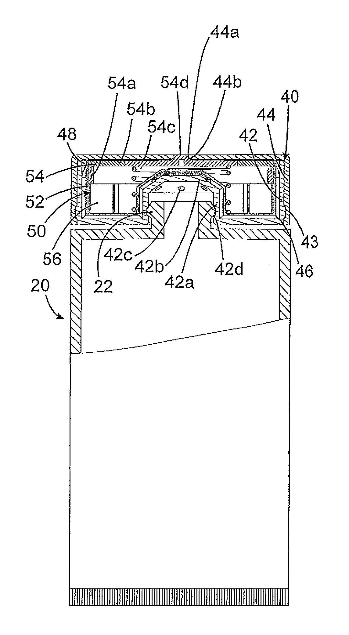
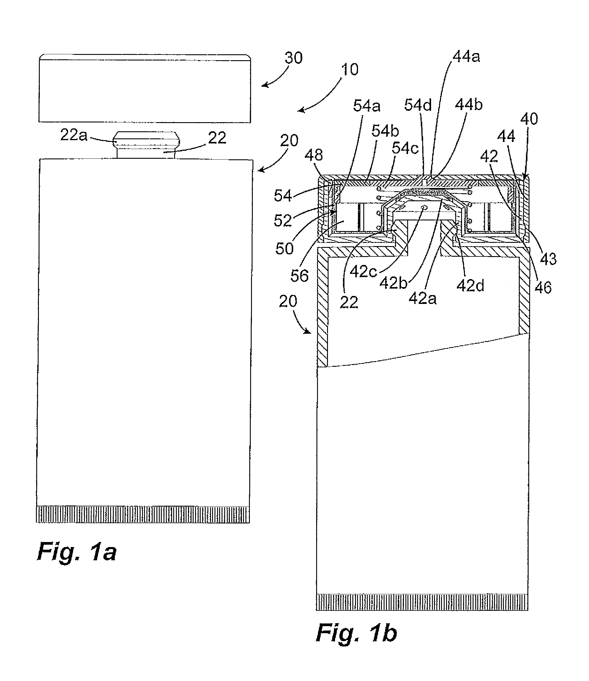
[0024]FIGS. 1a and 1b show a tube 10 according to the invention having a tube body 20 and a dispensing head 30 according to the invention. Therein, FIG. 1a shows the tube 10 according to the invention in a non-sectional illustration and in a not yet assembled condition of the dispensing head, and FIG. 1b shows the tube according to the invention in a completely assembled condition in a partially sectional view. As apparent from FIG. 1b, the dispensing head 30 includes an outer housing 40, which housing is composed of an inner shell 42 and an outer shell 44. The shells are fixedly secured and immobilized relative to another by detent means 43. The inner shell 42 defines a central receiving chamber 32 surrounded by an annular wall 42a of the inner shell 42. An end face wall 42b is provided on the bottom of the receiving chamber 32, wherein inlet openings 42c are provided to allow supply of medium into the dispensing head 30 through the inlet opening 42c. The receiving chamber 32 is ar...


PUM


Abstract

A dispensing head for a tube with a housing having a receiving chamber an outlet fitting of the tube an outlet opening, and an interior space surrounded by walls of the housing. An annular wall section of the housing separates the receiving chamber from an annular area of the interior space of the housing, an outlet valve is provided in the interior space, the outlet valve having a valve body, a valve seat and a pressure chamber designed so that the valve body and the valve seat are movable from a closed position to an open position by pressurization of the medium contained in the pressure chamber in order to allow discharge of the medium through the discharge opening. A medium path is provided within the housing, which connects an inlet opening to the pressure chamber.

Description

FIELD OF APPLICATION AND PRIOR ART[0001]The invention relates to a dispensing head for a tube for discharge of medium from the tube with a flat outer housing having on the rear end face facing the tube a receiving chamber for inserting and fixing an outlet fitting of the tube and on an opposite end face an outlet opening for discharge of the medium; an interior space surrounded by walls of the outer housing, wherein an annular wall section of the outer housing separates the receiving chamber from an annular area of the interior space of the outer housing that surrounds the annular wall section on the outside; an outlet valve provided in the interior space, the outlet valve having a valve body and a valve seat and a pressure chamber, which chamber is designed in such a way that the valve body and the valve seat can be spaced to each other from a closed position to an open position by pressurization of the medium contained in the pressure chamber, in order to permit discharge of the m...

Claims


Application Information

Patent Timeline
Patent Type & Authority Patents(United States)
IPC IPC(8): B65D25/40B65D83/44B65D35/46B65D35/08B65D47/20
CPCB65D83/44B65D35/46B65D47/2068B65D35/08B65D47/20B65D47/2018B65D47/2075
Inventor BRALL, DOMINIK
Owner APTAR RADOLFZELL
Why Eureka
Try Eureka