Phase-change memory cells

a memory cell and phase-change technology, applied in the field of phase-change memory cells, can solve the problems of destroying information, amorphous phase of phase-change materials showing undesirable attributes, and complicating the read out of stored information

Active Publication Date: 2015-07-21
GLOBALFOUNDRIES US INC
View PDF12 Cites 4 Cited by
  • Summary
  • Abstract
  • Description
  • Claims
  • Application Information

AI Technical Summary

Problems solved by technology

One of these is that the amorphous phase of phase-change materials exhibits undesirable attributes such as low-frequency noise and drift.
This complicates read out of the stored information, potentially even destroying the information if there is a large variability in the drift exhibited by different cell states so that the read measurement distributions for neighboring cell states interfere with one another.
The larger the number of cell states, and so closer the initial spacing between readback resistance levels, the more susceptible cells are to this problem.
Cell efficiency, which depends on the current / power required to program a PCM cell, presents another challenge.
This makes it difficult to sense the high resistance levels associated with the multiple programmed states.
A further challenge is the occurrence of “thermal disturb”.
Mushroom cells are easier to fabricate than confined cells, but have serious issues with cell efficiency and thermal disturb in addition to the drift effects discussed above.
Confined cells offer improved cell efficiency, but fabrication of these confined cell structures is especially challenging, particularly if filling of high-aspect ratio trenches with chalcogenides is required.

Method used


Image

  • Phase-change memory cells
  • Phase-change memory cells
  • Phase-change memory cells

Examples


Embodiment Construction

[0039]Preferred embodiments of the invention will now be described, by way of example, with reference to the above-mentioned drawings.

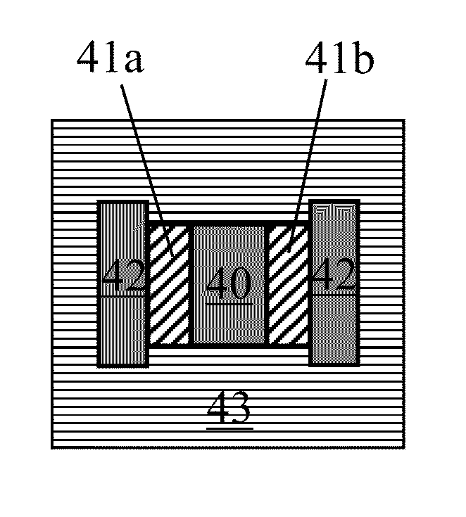
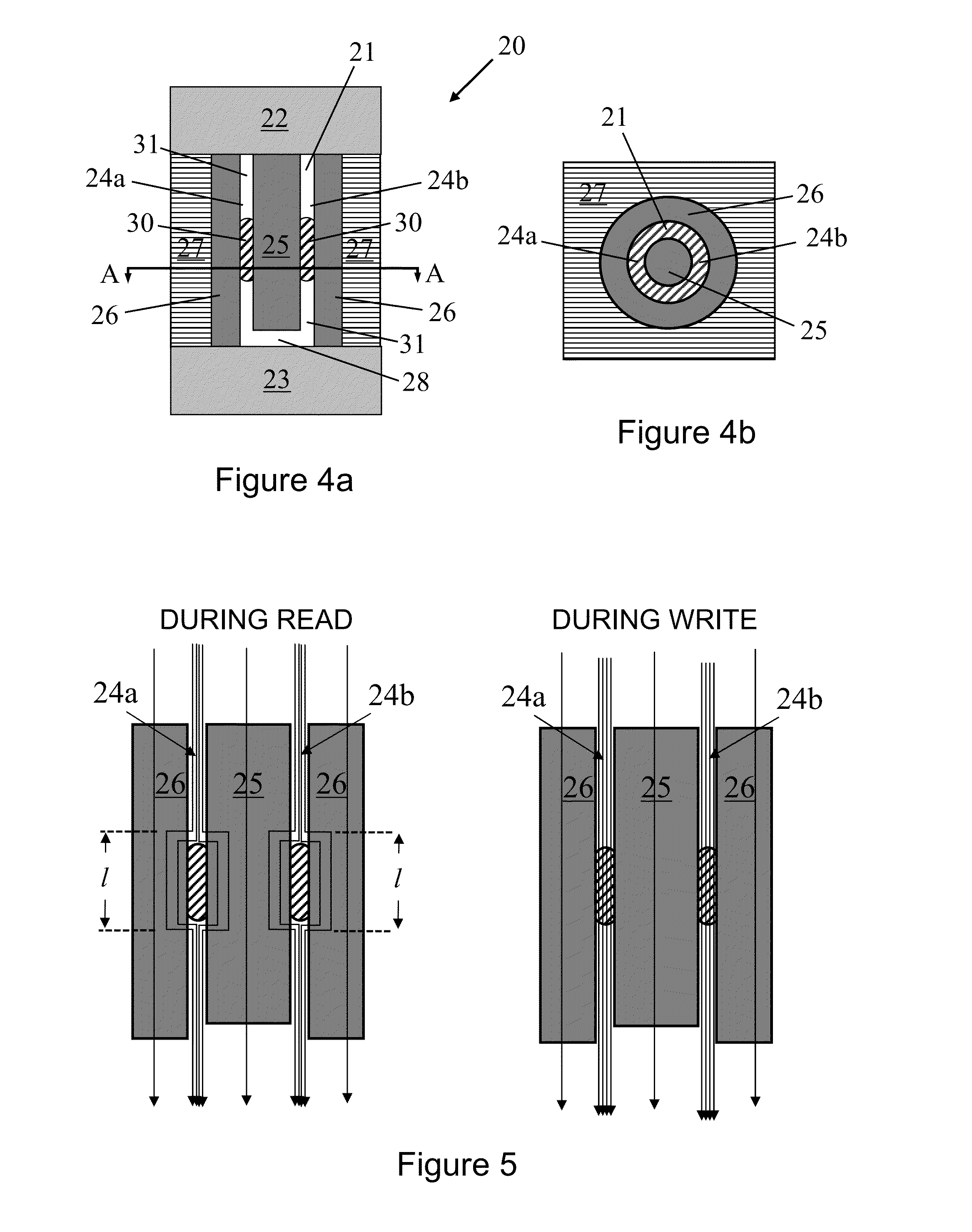
[0040]In PCM cells embodying the invention, the phase-change component has opposed layers of phase-change material extending in a direction between the electrodes. The core component is located on the inside of these opposed layers and the outer component is located on the outside of the opposed layers, each of these two components extending in a direction between the electrodes. At least one of these two components is arranged to present a lower-resistance path to the cell read current than the amorphous phase of the phase-change material. The arrangement is such that the length of this current path depends on size of the amorphous phase in the opposed layers, and thus on programmed cell state. Embodiments of the invention may offer high-performance PCM cells with reduced dimensions.

[0041]The PCM cell volume is determined by the thickness of the oppo...


PUM


Abstract

Phase-change memory cells for storing information in a plurality of programmable cell states. A phase-change component is located between first and second electrodes for applying a read voltage to the phase-change component to read the programmed cell state. The component includes opposed layers of phase-change material extending between the electrodes. A core component extends between the electrodes in contact with respective inner surfaces of the opposed layers. An outer component extends between the electrodes in contact with respective outer surfaces of the opposed layers. At least one of the core and outer component is formed of electrically-conductive material and is arranged to present, to a cell current produced by the read voltage, a lower-resistance current path than the amorphous phase of the phase-change material in any of said cell states. The current path has a length dependent on size of the amorphous phase in the opposed layers.

Description

CROSS-REFERENCE TO RELATED APPLICATION[0001]This application claims priority under 35 U.S.C. §119 from European Patent Application No. 1311670.2 filed Jun. 28, 2013, the entire contents of which are incorporated herein by reference.BACKGROUND OF THE INVENTION[0002]1. Field of the Invention[0003]This invention relates generally to phase-change memory cells. More specifically, the present invention relates to a phase-change memory cell for storing information in a plurality of programmable cell states.[0004]2. Description of Related Art[0005]Phase-change memory (PCM) is a non-volatile solid-state memory technology that exploits the reversible, thermally-assisted switching of phase-change materials, in particular chalcogenide compounds such as GST (Germanium-Antimony-Tellurium), between states with different electrical resistance. The fundamental storage unit (the “cell”) can be programmed into a number of different states, or levels, which exhibit different resistance characteristics....

Claims


Application Information

Patent Timeline
Patent Type & Authority Patents(United States)
IPC IPC(8): H01L45/00G11C13/00G11C11/56
CPCH01L45/1293G11C11/5678G11C13/0004G11C13/004G11C13/0069H01L45/1233H01L45/1253H01L45/1683G11C2213/15G11C2213/18G11C2213/52H10N70/8265H10N70/8616H10N70/231H10N70/068H10N70/8828H10N70/826H10N70/066H10N70/841
Inventor KREBS, DANIELSEBASTIAN, ABU
Owner GLOBALFOUNDRIES US INC
Why Eureka
Try Eureka