Livestock stanchion

a technology for stanchions and livestock, which is applied in the field of livestock stanchions, can solve the problems of reducing the service life so as to improve and improve the size of the livestock opening. , the effect of improving the maintenance and removal of the locking bar

Active Publication Date: 2015-07-28
DASILVEIRA SOUTHWEST INC
View PDF23 Cites 1 Cited by
  • Summary
  • Abstract
  • Description
  • Claims
  • Application Information

AI Technical Summary

Benefits of technology

[0016]The improved stanchion comprises a plurality of forked vertical posts fixed between a substantially horizontal base rail and a horizontal rail to form an essentially co-planar frame with a plurality of livestock openings to simultaneously achieve a sturdy and easily built frame with a minimal number of additionally shaped vertical support members. The improved stanchion may also include a serpentine shaped horizontal rail to increase the size of the livestock openings. A locking bar resting horizontally in at least two releasable support yokes mounted to the horizontal rail forms a swing space between the locking bar and the horizontal rail. The locking bar rotates about a longitudinal axis parallel to the base rail in at least two releaseable support yokes fixed to the horizontal rail. The releaseable support yokes provide ease of maintenance and removal of the locking bar (in one piece) from the improved stanchion without the need for cutting the locking bar. The locking bar of the improved livestock stanchion may include an end lap to releaseably couple two adjacent locking bars to further improve maintenance and removal of a locking bar. An offset of the pivot point between the forked frame and a pivoting restraining stanchion allows the neck of an animal sticking through a livestock opening to engage the restraining stanchion earlier than on existing pivoting restraining stanchions, thereby improving engagement of the restraining stanchion with the latching dogs fixed to the rotating locking bar. The improved livestock stanchion may further include an offset latching pin at the upper end of a restraining stanchion to improve early engagement of the restraining stanchion with the latching dogs.
[0017]It is the general object of the present invention to provide an low cost, easy to construct and maintain animal actuated locking and user activated unlocking livestock stanchion.
[0018]It is another object of the present invention to provide an improved livestock stanchion by which individual animals may lock themselves quicker into a frame with minimal horn, ear and head strikes when the latch assembly is in a locked position, but may not lock themselves into a frame when the latch assembly is in an unlocked position.
[0019]It is still another object of the present invention to provide an improved livestock stanchion by which a user may safely and simultaneously releases all animals or releases individual animals.
[0020]It is still another object of the present invention to provide an improved livestock stanchion that has parts that are easily replaced.

Problems solved by technology

However, cutting free the damaged portion from the frame usually renders the locking bar useless or requires welding the locking bar pieces (new and old) in place above the frame rather than on a workbench.
Furthermore, none of the above referenced patents provide for a strong but releaseably coupled joint between adjacent locking bars, whether rotating, sliding or a combination of both.
Regardless of which version is used, the mechanism is limited to arresting movement of the restraining bar in only one direction.
A large distance between opposing latches increases the likelihood of an animal injuring itself when the restraining stanchion is in a locked position.
Too small a distance between opposing latches, while decreasing the likelihood of an animal injuring itself, interferes with unlocking the latching mechanism.
Too small an opening and the ears or horns of an animal will strike the frame and cause the animal to shy away from inserting its head into the livestock opening.
Yet in each of these stanchions, additional vertical members are required, which increase the cost and complexity of a livestock frame.
Yet none provide a means to encourage early engagement before the restraining stanchion is in a near vertical position.

Method used


Image

  • Livestock stanchion
  • Livestock stanchion
  • Livestock stanchion

Examples


Embodiment Construction

[0030]As required, detailed embodiments of the present invention are disclosed herein; however, it is to be understood that the disclosed embodiments are merely exemplary of the invention that may be embodied in various and alternative forms. The figures are not necessarily to scale, some features may be exaggerated or minimized to show details of particular components. Therefore, specific structural and function details disclosed herein are not to be interpreted as limiting, but merely as a basis for the claims and a representative basis for teaching one skilled in the art to variously employ in the present invention.

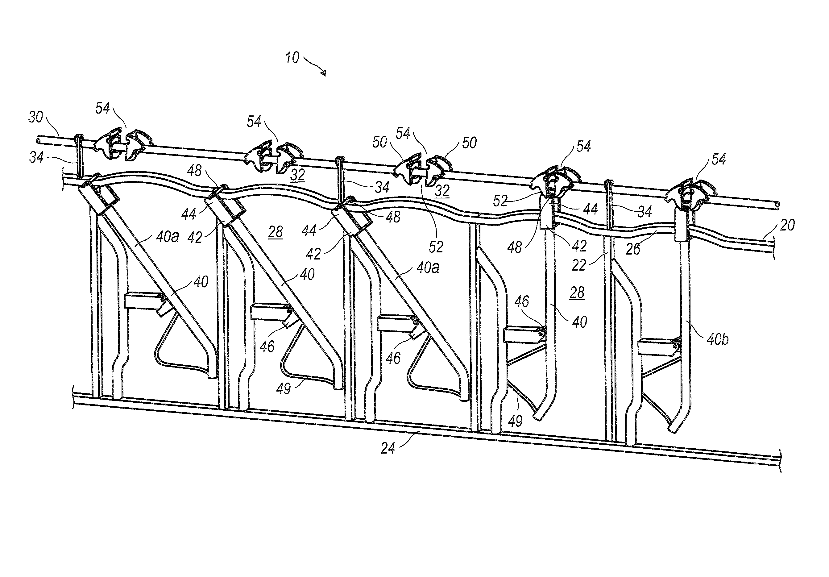
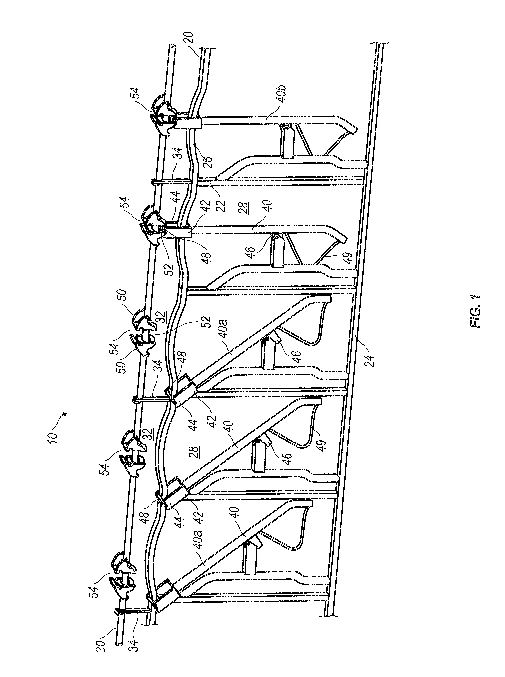
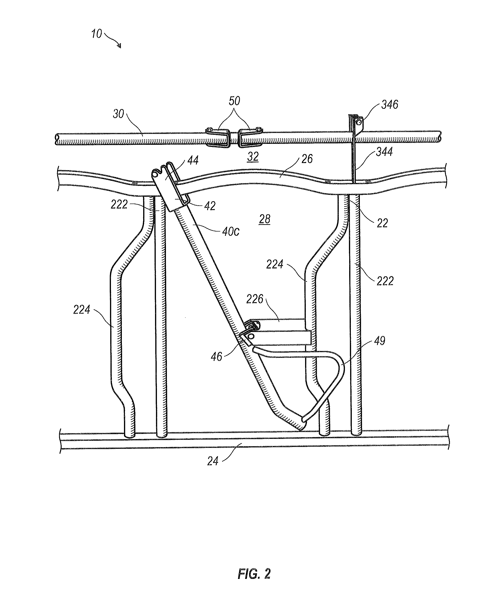
[0031]The present invention is directed toward a livestock stanchion 10 with a plurality of forked vertical posts 22 fixed between a substantially horizontal base rail 24 and a horizontal rail 26 to form an essentially co-planar frame 20 having at least one livestock opening 28. See FIGS. 1 and 2. In a preferred embodiment, vertical posts 22 are forked. In such an embo...


PUM


Abstract

An improved livestock stanchion including a plurality of forked vertical posts fixed between a substantially horizontal base rail and a horizontal rail to form a co-planar frame having at least one livestock opening. The horizontal rail can be serpentine in form to reduce the likelihood of head, horn or ear strikes as the animal's head enters a livestock opening. A locking bar rests in at least one releaseable support yoke mounted to the frame to allow easy installation and removal of a locking bar and its appurtenances. An end lap between adjacent locking bars provides for a strong releaseable couple. An offset pivot member and an offset latch pin of a pivoting restraining stanchion provide early engagement of a latch pin to a latching mechanism such as a pair of opposing latch dogs mounted on a locking bar above the horizontal rail.

Description

CROSS-REFERENCES TO RELATED APPLICATIONS[0001]Not ApplicableSTATEMENT REGARDING FEDERAL SPONSORED RESEARCH OR DEVELOPMENT[0002]Not ApplicableNAMES OF PARTIES TO A JOINT RESEARCH AGREEMENT[0003]Not ApplicableREFERENCE TO A SEQUENCE LISTING[0004]Not ApplicableBACKGROUND OF INVENTION[0005](1) Field of Invention[0006]The present invention relates generally to livestock stanchions. More particularly, the present invention relates to frames for livestock stanchions that allow easy locking and releasing of animals from a frame as well as ease of livestock stanchion maintenance.[0007](2) Background of Invention[0008]There exist a number of livestock stanchions that disclose an essentially co-planar frame of vertical and horizontal rails in combination with pivoting restraining stanchions to admit, restrain or manually release the heads of livestock. Typically, an animal is enticed to place its head through the frame to reach food that is typically on the other side of the frame and low to t...

Claims


Application Information

Patent Timeline
Patent Type & Authority Patents(United States)
IPC IPC(8): A01K15/04A01K1/06
CPCA01K1/0613A01K1/0606A01K15/04
Inventor DASILVEIRA, JOHN
Owner DASILVEIRA SOUTHWEST INC
Why Eureka
Try Eureka