Sheet material having a concave-convex part, and vehicle panel and laminated structure using the same

a technology of concave and convex parts and sheet materials, which is applied in the direction of transportation and packaging, layered products, building components, etc., can solve the problems that the desired stiffness increase effect cannot be obtained in another direction, and the effect cannot necessarily satisfy the demand, so as to improve damping characteristics, enhance the stiffness increase effect, and increase the stiffness

Active Publication Date: 2015-07-28
SUMITOMO LIGHT METAL INDS LTD
View PDF80 Cites 18 Cited by
  • Summary
  • Abstract
  • Description
  • Claims
  • Application Information

AI Technical Summary

Benefits of technology

[0056]Because it has such a structure, the sheet material has superior bending stiffness and surface stiffness as well as superior energy absorption characteristics.
[0063]In the vehicle panel, the sheet material that has the concave-convex part having high stiffness as mentioned above is used, in the outer panel or the inner panel, or both, and thereby it is possible to easily obtain a vehicle panel whose stiffness is extremely high. In addition, it is possible to obtain the effect of improving the damping characteristics attendant with the increase in stiffness, and to obtain the effect of improving the sound absorbing characteristics by virtue of containing air layers.

Problems solved by technology

Nevertheless, the stiffness of a sheet material provided with a corrugated shape has directionality, namely, there are cases wherein even though the stiffness increases in one direction, the desired stiffness increase effect is not obtained in another direction.
In addition, in the sheet material provided with the concave-convex part described in Patent Document 1, Patent Document 2, and the like, even though stiffness anisotropy is reduced, the stiffness increase effect thereof is approximately only two times and the weight reduction effect thereof is approximately only 20% of a flat sheet wherein the concave-convex part is not formed, and these effects cannot necessarily satisfy the demand.

Method used


Image

  • Sheet material having a concave-convex part, and vehicle panel and laminated structure using the same
  • Sheet material having a concave-convex part, and vehicle panel and laminated structure using the same
  • Sheet material having a concave-convex part, and vehicle panel and laminated structure using the same

Examples


embodiments

First Embodiment

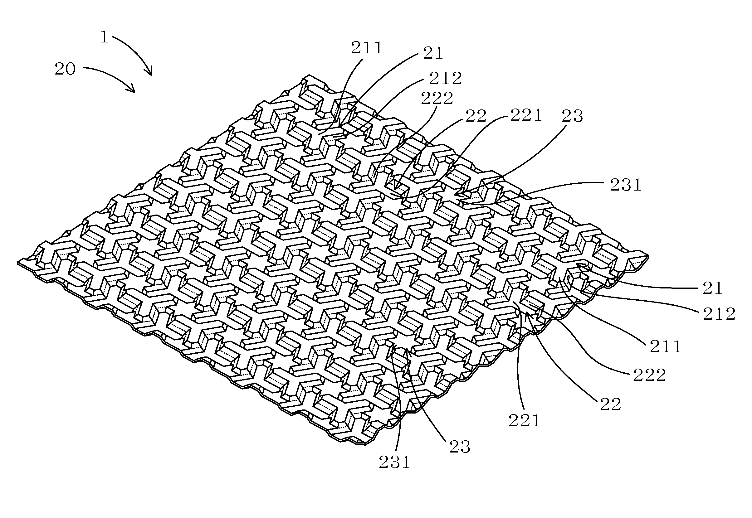
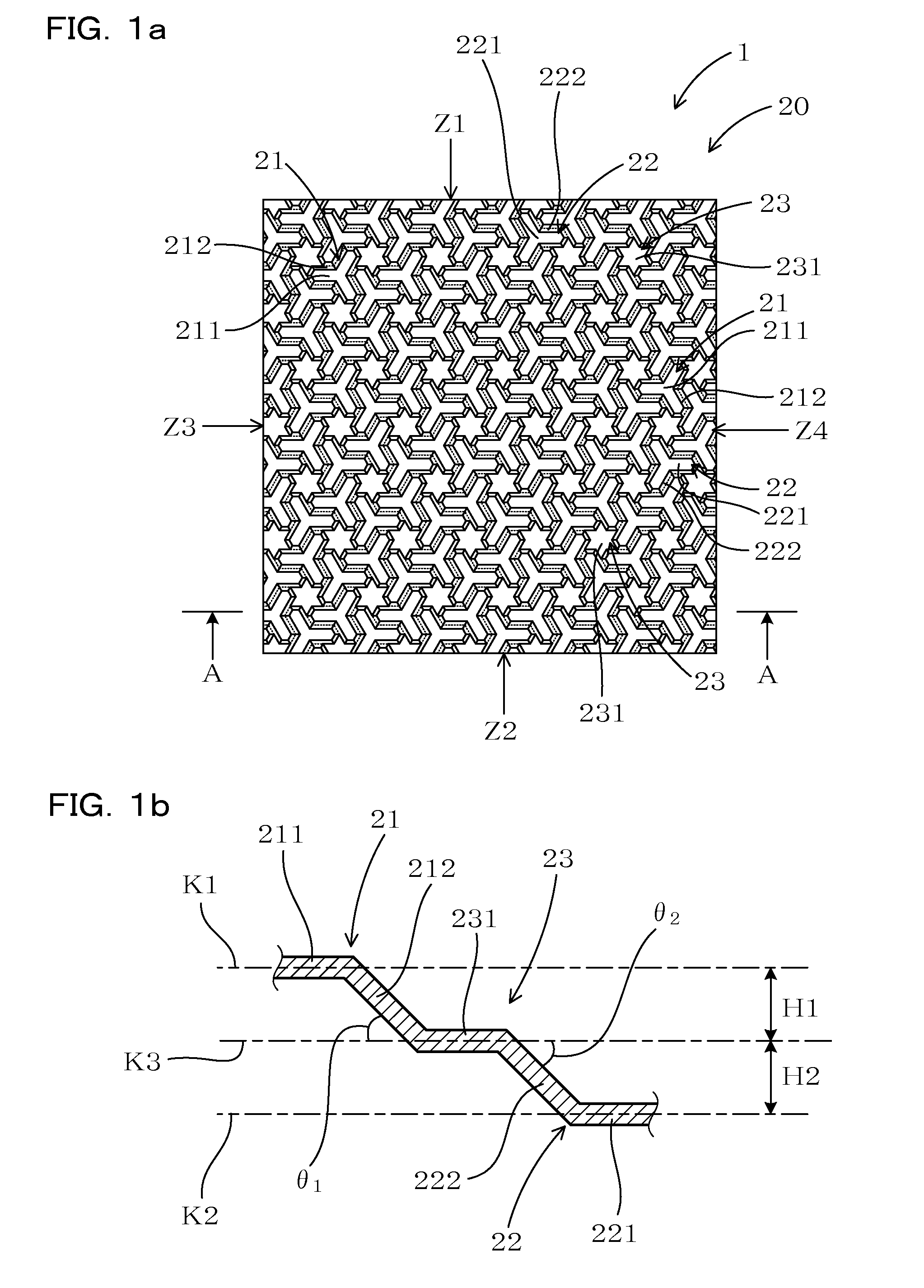
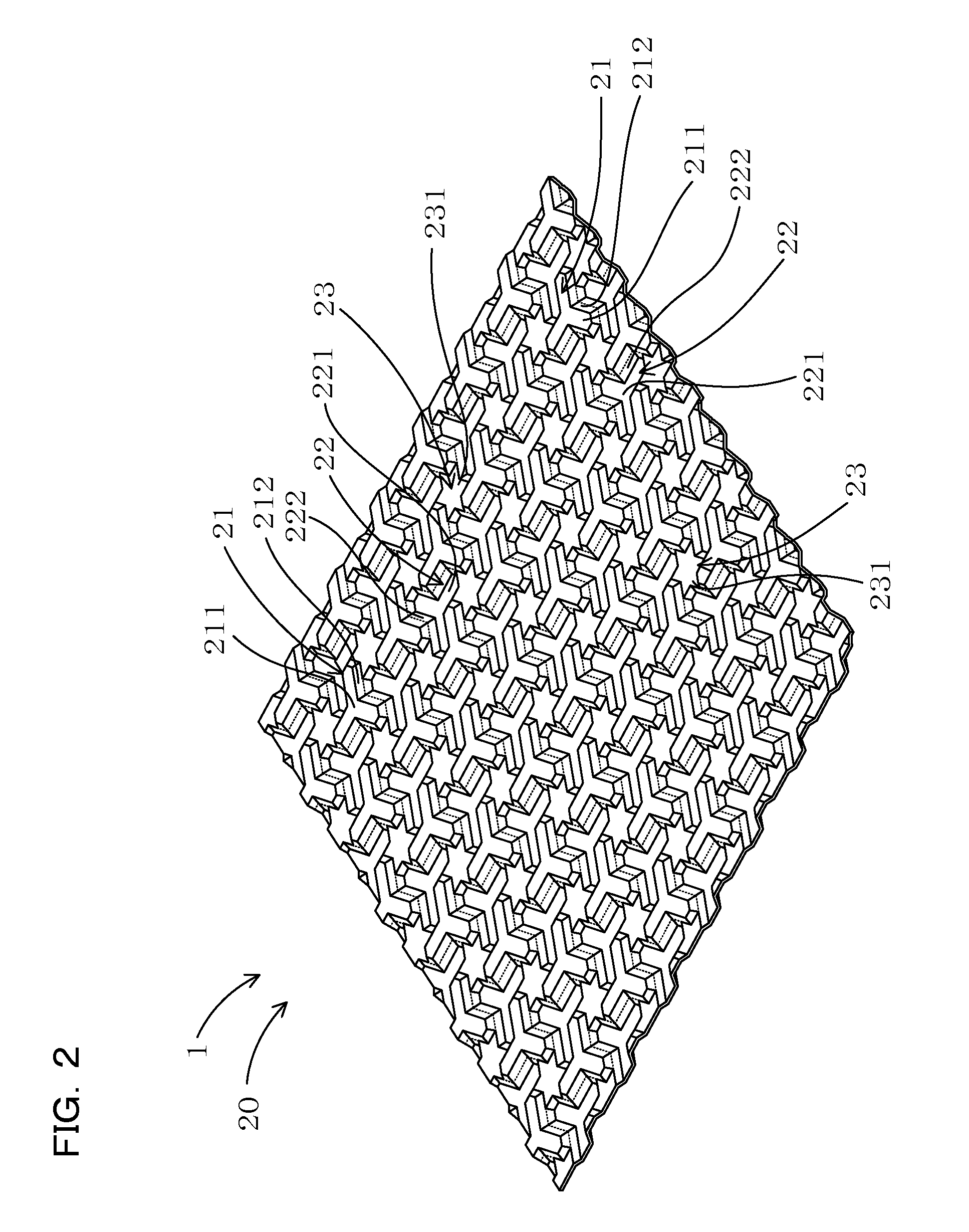
[0104]An embodiment of a sheet material 1 that has a concave-convex part 20 according to a first aspect will now be explained, referencing FIG. 1 through FIG. 3.

[0105]FIG. 1 is a partial plan view of the concave-convex part 20. Portions that are contours of new first areas 213 (FIG. 3) and new second areas 223 (FIG. 3) in an intermediate reference plane K3 in the same figure and are not visible as outlines are indicated by broken lines (the same applies to FIG. 2, FIG. 4, FIG. 5, and FIG. 12, which are discussed below).

[0106]In addition, FIG. 3 shows the shape of the concave-convex part 20 of the sheet material 1 as an arrangement of the new first reference areas 213, the new second reference areas 223, and new third reference areas 233 in the intermediate reference plane K3. In the same figure, the solid lines indicate contour lines of the new first reference areas 213, the new second reference areas 223, and the new third reference areas 233. In addition, the numer...

second embodiment

[0139]The present embodiment describes one example of the sheet material 1 that has the concave-convex part 20 according to a second aspect. In this example, after partitioning into the first reference areas 214, the second reference areas 224, and the third reference areas 234 in the same way as the first embodiment as shown in FIG. 3, all of the third reference areas 234 are distributed to the adjacent first reference areas 214 and the adjacent second reference areas 224 as shown in FIG. 6 such that the surface areas of the new first reference areas 213 and the new second reference areas 223 are substantially equal.

[0140]As shown in FIG. 4 through FIG. 6, the concave-convex part 20 of the present embodiment comprises: the first areas 21, which protrude from the new first reference areas 213 defined in the intermediate reference plane K3 toward the first reference plane K1; and the second areas 22, which protrude from the new second reference areas 223 defined in the intermediate r...

third embodiment

[0170]The present embodiment describes another example of the sheet material 1 that has a concave-convex part 20 according to a third aspect. In this example, after the intermediate reference plane K3 is partitioned into the first reference areas 214, the second reference areas 224, and the third reference areas 234 in the same way as the first embodiment as shown in FIG. 3, all of the third reference areas 234 are distributed to the adjacent second reference areas 224 as shown in FIG. 10. Other aspects of the configuration are the same as those in the first embodiment.

[0171]To quantitatively determine the stiffness increase effect of the sheet material 1 that has the concave-convex part 20 based on the intermediate reference plane K3 shown in FIG. 10, a bending stiffness evaluation of a cantilevered beam was performed using FEM analysis.

[0172]

[0173]The test piece used in the FEM analysis of a cantilevered beam has a rectangular shape measuring 120 mm×120 mm, and the concave-convex ...


PUM

PropertyMeasurementUnit
angleaaaaaaaaaa
inclination anglesaaaaaaaaaa
inclination angleaaaaaaaaaa

Abstract

A sheet material (1) includes a stiffness-increasing concave-convex part (20). A first reference plane (K1), an intermediate reference plane (K3), and a second reference plane (K2) serve as a reference system. The intermediate reference plane is partitioned by first lattice straight lines (L1), second lattice straight lines (L2), and third lattice straight lines (L3) so as to define hexagonal unit areas (24) and triangular unit areas (25) in the intermediate reference plane. Areas that include a plurality of the hexagonal unit areas and the triangular unit areas are designated as first, second and third reference areas (214, 224, 234), respectively. Combinations thereof constitute new first, second and third reference areas (213, 223, 233), respectively. The concave-convex part includes first areas (21) and second areas (22), which respectively include the new first reference areas and the new second reference areas, and third areas (23), which include the new third reference areas.

Description

CROSS-REFERENCE[0001]This application is the US national stage of International Patent Application No. PCT / JP2011 / 061476 filed on May 19, 2011, which claims priority to Japanese Patent Application No. 2010-200671, filed on Sep. 8, 2010.TECHNICAL FIELD[0002]The present invention relates to a sheet material whose stiffness is increased by the formation of a concave-convex part, and to a vehicle panel and a laminated structure that are configured using the same.BACKGROUND ART[0003]With the aim of reducing the weight of, for example, an automobile, the potential replacement of the material of components comprising steel sheets and the like with a lightweight material such as an aluminum alloy sheet is being studied and implemented. In such a case, assuming that the weight is reduced, it is necessary that the required stiffness be ensured.[0004]To date, studies conducted to increase stiffness without increasing the thickness of the sheet material have provided the sheet material with a c...

Claims


Application Information

Patent Timeline
Patent Type & Authority Patents(United States)
IPC IPC(8): B62D25/00B21D47/00B21D13/10E04C2/32B62D25/10B32B3/28
CPCB62D25/00B21D13/10B21D47/00B62D25/105E04C2/326B32B3/28B62D25/10Y10T428/24678
Inventor TAKAHASHI, MASAYA
Owner SUMITOMO LIGHT METAL INDS LTD
Why Eureka
Try Eureka